

-
Products -PCBA Manufacturing RF Connectors RF Cable Assemblys Embedded Antennas External Antennas GNSS Positioning Solutions
RF Connectors

RF Cable Assemblys
Embedded Antennas
External Antennas
GNSS Positioning Solutions































 Language


Language


Time:2026-10-16 Views:0
In an era where location data drives everything from autonomous vehicles to precision agriculture, the humble roof-mounted GNSS antenna has become a critical infrastructure component. Yet the most sophisticated GNSS receiver in the world becomes useless if its antenna succumbs to rain, dust, or high-pressure washdown. This is precisely why waterproof roof mount GNSS antennas have evolved from a niche accessory into a mission-critical hardware category.
A vehicle roof is arguably the most hostile environment for any antenna. It faces direct UV radiation, thermal cycling from −40 °C to +85 °C, vibration, salt spray, and in many fleet and industrial settings, routine high-pressure cleaning. The difference between an IP67 and an IP69K rating can mean the difference between reliable positioning for years and a maintenance nightmare that requires drilling out corroded hardware.
This guide provides a comprehensive engineering and procurement resource for anyone specifying, installing, or maintaining a waterproof roof mount GNSS antenna. We cover IP rating interpretation, electrical parameter trade-offs, multi-band frequency considerations, installation mechanics, cable loss management, and application-specific recommendations.
1. Understanding IP Ratings for Roof-Mounted GNSS Antennas
1.1 Decoding the IP Code
The Ingress Protection (IP) rating, governed by IEC 60529 and ISO 20653, uses two digits to quantify an enclosure's resistance to solids and liquids. The first digit (0–6) represents dust protection, with 6 denoting complete dust-tightness. The second digit (0–9K) indicates water resistance, and this is where the distinctions become critical for roof mount applications.
IP67: Protection against immersion in up to 1 meter of water for 30 minutes, plus complete dust ingress protection. This is widely considered the baseline “safety line” for permanent outdoor GNSS installations.
IP68: Withstands deeper or longer immersion, typically specified by the manufacturer.
IP69K: The highest washdown rating. Tested under IEC 60529 and ISO 20653, it certifies resistance to high-pressure water jets at 80–100 bar, with flow rates of 14–16 L/min at temperatures up to 80 °C.
Many premium roof mount GNSS antennas carry a dual rating such as IP67 / IP69K (after installation), meaning the antenna housing alone meets IP67, but the complete installed assembly achieves IP69K when proper sealing procedures are followed.
1.2 Matching IP Rating to Your Operating Environment
Selecting the right IP rating is an exercise in cost-benefit engineering. Over-specifying protection wastes budget that could be spent on superior RF performance; under-specifying guarantees premature failure.
Tier 1 — Sheltered or semi-enclosed installations (IP54–IP65). For antennas mounted inside vehicle cabins, under overhangs, or in climate-controlled enclosures, IP54 is often sufficient. The priority here should be gain and phase center stability rather than extreme sealing.
Tier 2 — General outdoor and vehicle roof (IP65–IP67). This covers the vast majority of fleet telematics, agricultural machinery, and RTK surveying applications. Rain, dust, and occasional splashing are the primary threats. IP67 provides robust protection, but attention must be paid to UV-resistant housing materials such as ASA (acrylonitrile styrene acrylate) or fiberglass composites to prevent embrittlement over 3–5 year deployment cycles.
Tier 3 — Extreme and corrosive environments (IP67–IP69K). Marine, mining, chemical processing, and rail applications demand the highest protection. Here, IP69K is essential if the antenna will encounter high-pressure washdown. Additionally, verify that the antenna has passed extended salt spray testing (96 hours minimum) and that all mounting hardware is 316 stainless steel or equivalent.
1.3 The Hidden Vulnerabilities: Cable Entry and Condensation
An IP69K rating on the antenna dome means little if water enters through the cable gland or connector interface. The most common failure mode in roof-mounted GNSS installations is not housing breach but water ingress through the cable entry point.
When evaluating a waterproof roof mount GNSS antenna, confirm:
The connector interface itself is IP67-certified (N-type or TNC connectors with self-sealing gaskets are preferred).
The sealing gasket material is silicone rubber rated for −40 °C to +85 °C and is user-replaceable.
Large dome antennas include a hydrophobic breather membrane (pressure equalization vent) to prevent internal condensation during thermal cycling.
2. Critical Electrical Specifications for Roof Mount GNSS Antennas
2.1 LNA Gain and Noise Figure
Because GNSS signals arrive at the Earth's surface with extremely low power (approximately −130 dBm for L1 C/A), virtually all roof mount antennas are active, incorporating a Low Noise Amplifier (LNA) directly in the antenna housing. The LNA gain and noise figure are the two most consequential RF parameters.
Typical LNA gain values for vehicular roof mount GNSS antennas range from 26 dB to 32 dB, with 28 ± 2 dB being the industry norm. The noise figure — a measure of how much the LNA degrades the signal-to-noise ratio — should be ≤ 2.0 dB, with premium models achieving ≤ 1.5 dB. Every 0.5 dB reduction in noise figure directly improves the carrier-to-noise density (C/N₀) reported by the receiver, which translates to faster time-to-first-fix and more reliable tracking in urban canyons or under tree canopy.
2.2 VSWR and Impedance Matching
Voltage Standing Wave Ratio (VSWR) quantifies how efficiently power transfers from the antenna to the feedline. For GNSS roof mount antennas, a VSWR of < 2.0:1 across the operating band is standard, while high-performance models achieve < 1.5:1. Poor VSWR indicates impedance mismatch, which reflects signal back toward the antenna, reducing effective gain and potentially causing receiver front-end desensitization.
All GNSS antennas and associated coaxial cable should be designed for 50 Ω impedance, the universal standard for RF systems.
2.3 Polarization: RHCP and Why It Matters
GNSS satellites transmit right-hand circularly polarized (RHCP) signals. A roof mount GNSS antenna must therefore be RHCP to maximize signal capture. Linear polarization, while common in LTE and Wi-Fi antennas within combo housings, is fundamentally mismatched to GNSS signals and incurs a theoretical 3 dB polarization loss.
2.4 Multi-Band Frequency Coverage
Modern GNSS constellations broadcast on multiple frequencies. A roof mount antenna's frequency coverage determines which signals it can receive:
L1 band (1559–1606 MHz): GPS L1, Galileo E1, GLONASS G1, BeiDou B1. This is the legacy core band.
L2 band (1217–1254 MHz): GPS L2, GLONASS G2. Critical for ionospheric correction in dual-frequency receivers.
L5 band (1164–1189 MHz): GPS L5, Galileo E5a, BeiDou B2a. Offers higher power and improved resistance to multipath, essential for RTK and safety-of-life applications.
L6 / E6 band (1278.75 MHz): QZSS L6 and Galileo E6. Used for precise point positioning (PPP) correction services.
A high-end multi-band roof mount GNSS antenna such as the Taoglas Colosseum X XAHP.50 covers GPS/QZSS L1/L2/L5/L6, Galileo E1/E5a/E5b/E6, GLONASS G1/G2/G3, BeiDou B1/B2a/B2b/B3, and L-band correction services in a single dome. For RTK and precision agriculture applications, L1/L2/L5 coverage is strongly recommended.
3. Phase Center Stability and Multipath Mitigation
3.1 Why Phase Center Stability Matters
For surveying, machine control, and autonomous navigation, phase center stability is arguably the most important antenna specification after waterproofing. The phase center is the apparent point from which the antenna receives satellite signals; if it shifts as the satellite elevation angle changes, the receiver introduces position errors that differential correction cannot fully remove.
High-quality roof mount GNSS antennas achieve phase center stability of < 2.0 mm through multi-point antenna feed designs and optimized element geometry. This level of stability is what enables centimeter-level RTK positioning on moving vehicles.
3.2 Multipath Rejection Through Radiation Pattern Design
Multipath — the reception of reflected satellite signals from the vehicle roof, surrounding structures, or the ground — is the dominant error source in urban and semi-urban GNSS positioning. Antennas designed for roof mount applications mitigate multipath through:
Broad axial ratio: A well-designed RHCP antenna maintains circular polarization purity across the upper hemisphere, rejecting cross-polarized reflected signals.
Low back radiation: The antenna should suppress signals arriving from below the horizon, where ground reflections originate.
Choke rings or corrugated ground planes: On high-end survey-grade antennas, these structures create a null toward low elevation angles, physically rejecting multipath.
The Colosseum X series, for example, achieves its multipath resilience through “even gain across the hemisphere that gives a good broad axial ratio,” which in turn provides excellent phase center stability.
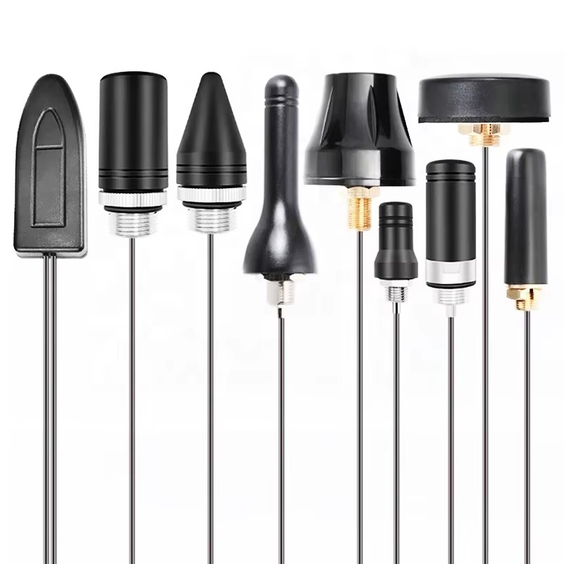
4. Installation Best Practices for Waterproof Roof Mount GNSS Antennas
4.1 Mounting Location Selection
The installation location determines 80% of real-world GNSS performance. Key principles:
1. Center of the roof: A metal vehicle roof acts as a ground plane, improving antenna gain and radiation pattern fidelity. The geometric center minimizes multipath asymmetry.
2. Clear sky view: The antenna should have an unobstructed view of the sky, ideally with a zenith angle clearance of at least 120°.
3. Distance from other antennas: Maintain a minimum of 1 meter from existing roof structures, and avoid proximity to high-power transmitters (VHF/UHF radios, radar).
4. Ground plane size: A conductive ground plane of at least 250 mm × 250 mm is recommended for optimal performance. Larger ground planes improve multipath rejection and gain stability.
4.2 Mechanical Mounting and Sealing
Proper mechanical installation is inseparable from waterproofing. The following procedure reflects best practices from leading manufacturers such as Panorama Antennas:
Step 1 — Surface preparation. The mounting surface must be flat, clean, and free of paint or coatings that could compromise the sealing gasket's compression. Check conductivity in the contact areas using an ohmmeter to ensure a low-resistance ground path.
Step 2 — Hardware selection. Use stainless steel M12 cap head bolts, nuts, and washers. Apply the supplied bonded sealing washers (e.g., Dowty washers) to each bolt. Tighten to 6 Nm torque — excessive torque deforms the gasket; insufficient torque fails to seal.
Step 3 — Sealing for IP69K. For installations requiring IP69K, apply a suitable sealant into each bolt location around the bolt heads, fit the plastic caps, and apply a continuous bead of silicone sealant around the edge of the antenna base where it meets the mounting panel.
Step 4 — Earthing. For antennas mounted on non-conductive panels (fiberglass truck caps, plastic fairings), a conductive mounting plate and earthing cable must be employed. Adequate earthing is critical not only for electrical safety but also for antenna performance, as the ground plane affects radiation pattern and VSWR.
4.3 Cable Routing and Drip Loops
The coaxial cable is the antenna's lifeline — and its most vulnerable point. A drip loop (a downward U-shaped bend) should be formed immediately before the cable enters the vehicle interior. This prevents water from traveling along the cable jacket and into the connector. Additionally, use cable ties or P-clamps to provide strain relief every 300 mm, preventing vibration-induced stress on the connector interface.
5. Cable Loss, Connectors, and the Link Budget
5.1 Cable Loss: The Silent Performance Killer
Every meter of coaxial cable attenuates GNSS signals. At the L1 frequency (1575.42 MHz), the loss characteristics of common cable types are:
| Cable Type | Loss at 1575 MHz (dB/100 m) | Max Length for 18 dB Loss |
|---|---|---|
| RG‑174 | ~90 dB | ~20 m |
| RG‑58 | ~55 dB | ~33 m |
| LMR‑300 | ~25 dB | ~72 m |
| LMR‑400 | ~17 dB | ~105 m |
Data adapted from industry feedline loss references.
For permanent roof mount installations with cable runs exceeding 3 meters, LMR-400 or equivalent low-loss coaxial cable is strongly recommended. The guiding principle is simple: the LNA gain minus all cable and connector losses should leave sufficient signal for the receiver. Trimble, for example, recommends no more than 35 dB remaining gain at the receiver input.
5.2 Connector Selection
For waterproof roof mount GNSS antennas, the connector interface must be evaluated as part of the sealing system:
N-type connectors: The preferred choice for permanent outdoor installations due to their weather-resistant threaded coupling and robust construction. Many survey-grade antennas use an N-type female jack on the antenna and a mating N-type male on the cable.
TNC connectors: Common in automotive and fleet applications where a smaller form factor is required. Threaded coupling provides better vibration resistance than BNC.
SMA connectors: Found on compact antennas and combo housings, but generally not recommended for the antenna-to-cable interface in permanent outdoor installations due to lower weather resistance.
Each connector pair adds approximately 0.1–0.3 dB of insertion loss. Minimize the number of connectors in the signal path.
6. Application-Specific Recommendations
6.1 Fleet Telematics and Asset Tracking
Fleet management demands a balance of durability, cost, and multi-band capability. A 2-in-1 or 3-in-1 combo antenna combining GNSS with 4G/5G MIMO and Wi-Fi reduces roof clutter and installation time. The Taoglas Stingray II (MA290.A) exemplifies this category: IP67-rated, with GNSS and 5G/Wi-Fi in a single adhesive-mount housing designed for telematics and fleet management.
Key specifications to prioritize: IP67 minimum, LNA gain ≥ 26 dB, noise figure ≤ 2.0 dB, and support for GPS/GLONASS/Galileo/BeiDou.
6.2 Precision Agriculture and Machine Control
RTK-guided tractors, combines, and sprayers require centimeter-level accuracy. Here, multi-band (L1/L2/L5) coverage with phase center stability < 2 mm is non-negotiable. The antenna must also withstand chemical exposure from fertilizers and pesticides, making IP69K and chemical-resistant housing materials essential.
6.3 Surveying and Construction
Survey-grade roof mount antennas, whether mounted on a vehicle or a temporary mast, prioritize phase center stability, multipath rejection, and L1/L2/L5/L6 coverage. The Joymax PPX-095ANF4W exemplifies this class: IP67-rated, integrated two-stage LNA, RHCP polarization, and support for GPS, Galileo, GLONASS, BeiDou, and IRNSS in a low-profile dome that can be permanently mounted on a vehicle roof or metal surface.
6.4 Marine and Offshore
Salt spray is the defining environmental threat. Specify IP67/IP69K with 96-hour salt spray certification and 316 stainless steel hardware. Housing material should be ASA or glass-fiber reinforced composite. A hydrophobic breather membrane is highly recommended to manage internal condensation caused by the extreme day-night thermal cycling at sea.
7. Frequently Asked Questions
Q: Can I mount a GNSS antenna on a plastic or fiberglass roof?
Yes, but you must provide an artificial ground plane. A conductive mounting plate of at least 250 mm × 250 mm should be bonded to the vehicle chassis with a dedicated earthing cable. Without a ground plane, antenna gain and multipath rejection degrade significantly.
Q: How do I know if my antenna's IP69K rating is genuine?
Request the test report. IP69K certification under IEC 60529 or ISO 20653 specifies spray distance, pressure (80–100 bar), flow rate (14–16 L/min), temperature (80 °C), and exposure duration. Reputable manufacturers publish these certificates. Be wary of “IP69K-compatible” claims without documentation.
Q: Is a magnetic mount GNSS antenna waterproof enough for permanent use?
Magnetic mounts are designed for temporary testing, not permanent installation. They lack the mechanical fastening and gasket compression required for sustained IP67/IP69K sealing. For any deployment lasting more than a few days, use a bolt-through or screw-mount antenna.
Q: What causes a roof mount GNSS antenna to fail prematurely?
The three most common failure modes are: (1) water ingress through the cable entry point, often due to a missing drip loop or degraded cable jacket; (2) corrosion of mounting hardware, particularly when dissimilar metals are used without isolation; and (3) UV degradation of the housing material, causing cracks that breach the seal. Each is preventable with correct specification and installation.
Q: Do I need a lightning arrestor for a vehicle roof GNSS antenna?
For vehicle-mounted antennas, the vehicle chassis provides a degree of protection, but a coaxial lightning arrestor is still recommended if the vehicle is parked in an exposed area during thunderstorms. The arrestor must be installed in the cable run close to the receiver and bonded to a low-impedance ground. For fixed rooftop installations (buildings, towers), a lightning protection system is mandatory.
8. Buying Guide: Specification Checklist
When procuring a waterproof roof mount GNSS antenna, use this checklist to compare options systematically:
| Parameter | Minimum Requirement | Recommended for Critical Applications |
|---|---|---|
| Ingress Protection | IP67 | IP67 / IP69K (after installation) |
| Frequency Bands | L1 (GPS/Galileo/GLONASS/BeiDou) | L1/L2/L5 + L-band |
| LNA Gain | 26 dB | 28–32 dB |
| Noise Figure | ≤ 2.0 dB | ≤ 1.5 dB |
| VSWR | < 2.0:1 | < 1.5:1 |
| Polarization | RHCP | RHCP with axial ratio < 3 dB |
| Phase Center Stability | < 5 mm | < 2 mm |
| Operating Temperature | −40 °C to +85 °C | −40 °C to +85 °C |
| Salt Spray | 48 h | 96 h |
| Housing Material | ASA or UV-stabilized ABS | ASA or fiberglass composite |
| Mounting Hardware | 304 stainless steel | 316 stainless steel |
| Connector Type | TNC or SMA | N-type (permanent outdoor) |
A waterproof roof mount GNSS antenna is not a commodity component — it is a precision RF instrument operating in one of the harshest environments imaginable. The difference between a system that delivers reliable centimeter-level positioning for a decade and one that fails within eighteen months lies in the details: a properly rated IP seal, a cable entry protected by a drip loop, a noise figure measured in tenths of a decibel, and a phase center stable to within two millimeters.
By applying the selection criteria, installation practices, and application-specific recommendations outlined in this guide, engineers and fleet managers can specify waterproof roof mount GNSS antennas with confidence — ensuring that the critical location data their systems depend on remains available when it matters most. The antenna may be the smallest line item in a GNSS budget, but it is the one component that, if neglected, can bring the entire positioning chain to a halt.
Lucy Yang | lucy.y@toxutech.com
Dotty Zhao | sales04@toxutech.com
Global Business Director / Sales Team / Global Operations


 En
En Cn
Cn Korean
 Home >