

-
Products -PCBA Manufacturing RF Connectors RF Cable Assemblys Embedded Antennas External Antennas GNSS Positioning Solutions
RF Connectors

RF Cable Assemblys
Embedded Antennas
External Antennas
GNSS Positioning Solutions































 Language


Language


Time:2026-10-15 Views:0
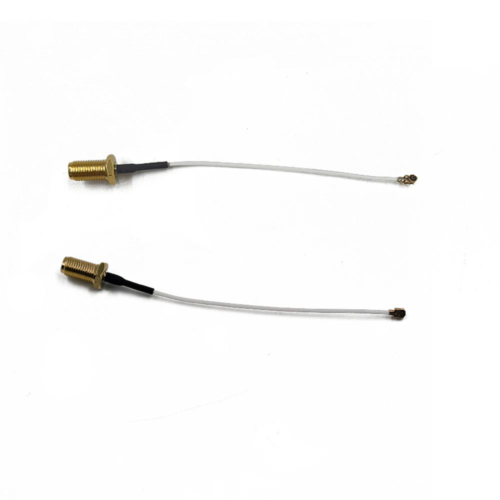
U.FL to SMA cable assembly is one of the most widely used RF coaxial cable solutions for wireless communication devices, serving as a critical bridge between miniature internal PCB antenna ports and standard external SMA antenna interfaces. Also known as U.FL SMA pigtail cable, IPEX to SMA cable, or MHF to SMA jumper, this cable assembly enables seamless signal transmission for WiFi, Bluetooth, LTE, 5G, LoRaWAN, GPS, and industrial IoT devices. Engineered for low signal loss, compact size, and high durability, U.FL to SMA cable assemblies are essential for electronic designers, DIY enthusiasts, network engineers, and industrial equipment manufacturers worldwide. This comprehensive guide covers everything you need to know about U.FL to SMA cable assemblies, including core specifications, cable types, key features, application scenarios, selection criteria, installation tips, and common troubleshooting problems, fully optimized for Google search engine visibility and industry user queries.
1. What Is a U.FL to SMA Cable Assembly?
A U.FL to SMA cable assembly is a preassembled coaxial RF cable with a U.FL (IPEX/MHF) connector on one end and an SMA (or RPSMA) connector on the opposite end. As a standardized RF transition cable, it solves the core pain point of mismatched antenna interfaces in miniaturized electronic devices: U.FL connectors are ultrasmall, surfacemount ports designed for compact PCB integration, while SMA connectors are robust, threaded, industrystandard interfaces for external antenna mounting and signal extension.
All professional U.FL to SMA cable assemblies adopt 50ohm impedance matching, the universal standard for wireless communication RF systems. This impedance consistency eliminates signal reflection, standing wave loss, and signal distortion during data transmission, ensuring stable and highefficiency RF signal output. Unlike custommade RF cables, factorypreassembled U.FL to SMA cable assemblies feature precise crimping, soldering, and shielding processing, with consistent electrical performance and mechanical reliability, making them plugandplay for most wireless device projects.
It is necessary to distinguish common alias terms for better search and product matching: U.FL connectors are often referred to as IPEX or MHF connectors in the industry, so IPEX to SMA cable and MHF to SMA cable are essentially the same product as U.FL to SMA cable assembly. Meanwhile, users often confuse SMA and RPSMA variants, which we will elaborate on in the following chapters to help users avoid selection errors.
2. Core Components & Technical Specifications of U.FL to SMA Cable Assembly
The performance of a U.FL to SMA cable assembly depends entirely on its three core components: U.FL terminal, coaxial cable body, and SMA terminal. Each component has strict technical parameters that determine the cable’s frequency range, signal loss, durability, and application compatibility. Below are the standardized technical specifications of mainstream U.FL to SMA cable assemblies in the global market.
2.1 U.FL (IPEX/MHF) Connector End
The U.FL connector is a microminiature RF connector developed for highdensity, compact electronic devices. It features a snapon mounting design, no threaded structure, and ultrasmall size, which saves valuable PCB space for miniaturized devices. Key specifications include:
Impedance: 50Ω (standard for all wireless RF communication)
Operating Frequency: DC ~ 6GHz, covering 2.4GHz WiFi, 5GHz WiFi, 4G LTE, 5G sub6GHz, Bluetooth, and LoRa frequencies
Contact Material: Highpurity copper with goldplated surface, ensuring low contact resistance, antioxidation, and long service life
Mechanical Lifespan: More than 300 plugandpull cycles, meeting longterm industrial use and daily equipment maintenance needs
Installation Method: Snapon type, easy to disassemble and assemble without professional tools
2.2 SMA/RPSMA Connector End
The SMA end is the external connection terminal of the cable assembly, used for connecting external antennas, RF test equipment, or device bulkhead interfaces. It is divided into two core types: standard SMA and RPSMA (Reverse Polarity SMA), which are the most critical selection indicators for users.
Standard SMA Connector: Male SMA has an outer thread and center pin; female SMA has an inner thread and center hole. Mainly used for industrial RF test equipment, base stations, and professional communication devices.
RPSMA Connector: Reverse polarity design swaps the pin and socket structure of standard SMA. It is the mainstream interface for consumer wireless devices such as WiFi routers, wireless network cards, drones, and IoT sensors. Standard SMA and RPSMA cannot be intermated, so users must confirm the interface type before purchasing.
In addition, SMA terminals support straight and rightangle (90degree) molding designs. Rightangle U.FL to SMA cable assemblies are suitable for narrow installation spaces and can avoid cable bending damage, while straight types are more suitable for conventional linear wiring scenarios. All SMA connectors adopt goldplated contacts and nickelplated shells, with excellent corrosion resistance and electromagnetic shielding performance.
2.3 Coaxial Cable Core Specifications
Different coaxial cable models directly determine the signal loss rate, bending resistance, temperature resistance, and size of the U.FL to SMA cable assembly. The three most common cable types in the market are RG1.13, RG178, and RG316, each with unique application advantages:
RG1.13 Cable: Ultrathin outer diameter (1.13mm), ultraflexible, suitable for ultracompact equipment such as miniature wireless modules, drone internal wiring, and wearable IoT devices. It features minimal space occupation and stable lowfrequency signal transmission, with a maximum frequency of up to 6GHz.
RG178 Cable: Outer diameter of 1.8mm, balanced in flexibility and signal loss. It is the most costeffective universal model, widely used in ordinary WiFi network cards, household routers, and small IoT devices. The signal loss is 1.8dB/m at 2.4GHz, fully meeting daily wireless communication needs.
RG316 Cable: Highperformance lowloss cable with 2.5mm outer diameter, FEP/PTFE hightemperature resistant insulation layer. It can withstand extreme temperatures from 65°C to +150°C, with ultralow signal loss (only 1.46dB/m at 2.4GHz). It is the preferred choice for industrial equipment, outdoor communication devices, and highfrequency 5G equipment.
All qualified U.FL to SMA coaxial cables adopt doublelayer shielding structure (braided copper mesh + aluminum foil shielding), which effectively isolates external electromagnetic interference (EMI) and ensures stable signal transmission in complex electromagnetic environments.
3. Main Types of U.FL to SMA Cable Assemblies
According to interface type, cable length, molding angle, and usage scenario, U.FL to SMA cable assemblies can be divided into multiple categories, helping users quickly select the matching model. Classified by mainstream market specifications, the main types are as follows:
3.1 By Interface Polarity
U.FL to Standard SMA Cable Assembly: Suitable for industrial RF testing, communication base stations, and professional wireless equipment, supporting standard SMA antenna connection.
U.FL to RPSMA Cable Assembly: The most popular consumergrade model, compatible with most WiFi routers, wireless adapters, Bluetooth modules, and drone antennas on the market.
3.2 By Connector Molding Angle
Straight U.FL to SMA Cable: Linear terminal design, suitable for open wiring environments, with no bending loss, ideal for fixed equipment installation.
RightAngle (90°) U.FL to SMA Cable: Vertical terminal design, solving the wiring dead angle of narrow equipment casings, avoiding excessive cable bending and core wire breakage, greatly improving installation flexibility.
3.3 By Cable Length
Mainstream conventional lengths include 10cm, 15cm, 20cm, 30cm, 50cm, 1m, 2m, and 3m. For highfrequency signals above 2.4GHz, industry standards recommend controlling the cable length within 5m to avoid excessive signal attenuation; for lowfrequency LoRa and GPS signals, the length can be extended to 10m for outdoor deployment. Custom length services are available for special industrial project needs.
3.4 By Cable Grade
Consumer Grade: RG1.13/RG178 material, costeffective, suitable for household wireless devices, daily DIY modification, and small civil IoT equipment.
Industrial Grade: RG316 hightemperature resistant lowloss cable, antiinterference, antiaging, and weatherresistant, suitable for outdoor equipment, industrial control devices, vehiclemounted communication modules, and longterm uninterrupted operating equipment.
4. Key Advantages of U.FL to SMA Cable Assembly
The widespread popularity of U.FL to SMA cable assemblies in the RF communication industry stems from their unique structural design and superior performance, which cannot be replaced by other adapter cables. The core advantages are summarized as follows:
4.1 UltraCompact & High Integration
The U.FL micro connector occupies an extremely small PCB area, which perfectly matches the miniaturization design trend of modern wireless modules, M.2 network cards, and embedded devices. Compared with traditional largesize RF connectors, U.FL to SMA cable assemblies greatly reduce the internal space occupation of equipment, enabling thinner and smaller electronic product design without sacrificing signal performance.
4.2 Low Signal Loss & Strong AntiInterference
With 50Ω precise impedance matching and doublelayer shielding structure, the cable assembly effectively reduces signal attenuation, standing wave fluctuation, and electromagnetic interference. Highpurity goldplated connectors ensure stable electrical contact, avoiding signal interruption or fluctuation caused by oxidation and poor contact. Even in complex industrial electromagnetic environments, it can maintain highquality RF signal transmission.
4.3 Flexible Installation & Wide Compatibility
The flexible coaxial cable body supports arbitrary bending and routing, adapting to various complex equipment internal structures. Multiple interface combinations and length options achieve full compatibility with mainstream wireless devices on the market, including WiFi 6/6E/7 modules, 4G/5G LTE modules, GPS positioning modules, LoRaWAN IoT nodes, drone communication systems, and SDR softwaredefined radio equipment.
4.5 Durable & CostEffective
Industrialgrade cable assemblies adopt hightemperature resistant FEP jackets and reinforced crimping technology, with excellent tensile resistance, antiaging, and weather resistance. The plugandplay design eliminates the need for professional welding and debugging, greatly reducing equipment assembly and maintenance costs. Compared with custom RF cables, standardized U.FL to SMA cable assemblies have lower unit prices and more stable quality, suitable for mass production and batch procurement.
5. Common Applications of U.FL to SMA Cable Assembly
U.FL to SMA cable assemblies cover almost all fields of wireless communication, from civil consumer electronics to industrial intelligent equipment, becoming a standard accessory for wireless signal extension. The main application scenarios are as follows:
5.1 Wireless Network Equipment
This is the most extensive application scenario. U.FL to SMA cable assemblies are used for internal wiring of WiFi routers, wireless AP, M.2 wireless network cards, and desktop wireless adapters. They connect the internal U.FL antenna interface of the network module to the external SMA highgain antenna, effectively improving WiFi signal coverage, solving the problem of weak signal and small coverage of builtin antennas, and enhancing network stability and transmission speed.
5.2 IoT & Industrial Communication Devices
In industrial IoT systems, U.FL to SMA cable assemblies are widely used in LoRaWAN gateways, industrial sensor nodes, 4G/5G CPE equipment, and smart city monitoring devices. Industrialgrade RG316 cable assemblies can adapt to harsh environments such as high temperature, low temperature, and strong electromagnetic interference in industrial sites, ensuring longterm stable operation of IoT communication signals and supporting remote data transmission of intelligent equipment.
5.3 Drone & Portable Electronic Equipment
Drones, portable Bluetooth devices, and wearable intelligent devices have strict requirements on equipment volume and weight. Ultrathin RG1.13 U.FL to SMA cable assemblies are lightweight and smallsized, suitable for internal antenna wiring of drones, solving the problem of short remote control distance and unstable image transmission signals. They are also commonly used for equipment maintenance and replacement of damaged original antenna cables.
5.4 GPS & VehicleMounted Communication Systems
Vehiclemounted GPS positioning modules, vehicle wireless communication terminals, and navigation equipment all rely on U.FL to SMA cable assemblies to extend GPS antennas. The lowloss transmission performance ensures accurate and stable positioning signals, avoiding positioning deviation or signal loss caused by poor antenna contact, and improving the positioning accuracy of vehiclemounted equipment.
5.5 RF Test & Experimental Equipment
In laboratory RF signal testing, SDR softwaredefined radio, and wireless equipment debugging, U.FL to SMA cable assemblies are used as signal transition lines to connect miniature test modules to professional SMA test instruments, realizing signal detection, parameter debugging, and equipment performance testing, which is an essential auxiliary tool for RF engineers and electronic developers.
6. How to Choose the Right U.FL to SMA Cable Assembly? (Complete Selection Guide)
Many users encounter problems such as interface mismatch, excessive signal loss, and inappropriate cable length after purchasing U.FL to SMA cable assemblies. To help users make accurate selections, we summarize a complete selection standard based on application scenarios, technical parameters, and equipment requirements:
6.1 Confirm Interface Polarity First
Distinguish between SMA and RPSMA interfaces: Consumer wireless devices (routers, network cards, drones) mostly use RPSMA; industrial test equipment and base stations mostly use standard SMA. Never mix the two, as they cannot be physically connected and will cause equipment failure.
6.2 Select Cable Model According to Frequency & Scenario
Household WiFi/Bluetooth (2.4G/5G): Choose RG178 cable, costeffective and fully meeting daily signal transmission needs.
Miniature devices (drones, wearable devices): Choose ultrathin RG1.13 cable, flexible and spacesaving.
Industrial outdoor/5G highfrequency equipment: Choose RG316 lowloss hightemperature resistant cable to reduce highfrequency signal attenuation and adapt to harsh environments.
6.3 Determine Reasonable Cable Length
Follow the core principle: the shorter the cable, the lower the signal loss. On the premise of meeting equipment routing and avoiding cable tension and sharp bending, choose the shortest possible length. For 2.4GHz lowfrequency signals, the maximum applicable length is 10m; for 5GHz/6GHz highfrequency signals, the length should be controlled within 5m to ensure signal integrity.
6.4 Select Molding Angle Based on Installation Space
For equipment with narrow internal space and vertical wiring limitations, choose rightangle U.FL to SMA cable assemblies to avoid cable folding and core wire damage; for open and straight wiring environments, choose straight cables for simpler installation and lower signal loss.
6.5 Prioritize HighQuality Shielding & Plating
Select goldplated connectors and doublelayer shielding cables. Goldplating can effectively prevent oxidation and ensure longterm stable contact, while doublelayer shielding can resist external electromagnetic interference, which is particularly important for industrial and highprecision communication equipment.
7. Standard Installation Steps & Precautions
Correct installation is the key to ensuring the performance of U.FL to SMA cable assembly. Improper installation will lead to increased signal loss, poor contact, or even cable damage. The standard installation steps and key precautions are as follows:
7.1 Installation Steps
1. Power off the equipment: Before installation, cut off all power of the wireless device to avoid short circuit and static damage to the module and cable.
2. Connect the U.FL end: Align the U.FL snapon connector with the PCB base, press it vertically and gently until a clear "click" sound is heard, indicating successful locking. Ensure the connector is fully attached without skew or looseness.
3. Route the cable reasonably: Arrange the cable along the internal gap of the equipment, avoid sharp bending, stretching, and extrusion, and reserve a certain margin for wiring.
4. Fix the SMA end: Screw the SMA connector onto the equipment bulkhead or antenna interface, tighten it moderately (do not overtwist to avoid thread damage), and ensure close contact.
5. Power on and test: After installation, power on the equipment, test signal strength, network speed, and communication stability to confirm normal operation.
7.2 Key Precautions
Do not bend the cable at an acute angle (bending radius shall not be less than 5 times the cable outer diameter) to prevent internal core wire breakage and shielding layer damage.
Avoid frequent plugging and unplugging the U.FL end excessively to prevent the snapon structure from loosening and affecting connection stability.
Do not pull the cable violently during installation and use to prevent connector falling off and internal wire disconnection.
For outdoor installation, select weatherresistant industrialgrade cables and do a good job of waterproof and dustproof treatment at the interface to extend service life.
8. Common Faults & Troubleshooting Solutions
In the use process of U.FL to SMA cable assemblies, users often encounter problems such as weak signal, unstable network, and no signal. The following summarizes common faults and targeted solutions to help users quickly solve problems:
8.1 Weak Wireless Signal & Low Transmission Speed
Causes
Solutions: Replace with a shorter highquality lowloss cable, rearrange the wiring to avoid bending, replug and fix the connector tightly, and confirm that SMA/RPSMA interface matches the equipment.
8.2 Unstable Signal & Frequent Disconnection
Causes: U.FL connector is not locked in place, interface oxidation, external electromagnetic interference, or cable shielding layer damage.
Solutions: Reinstall the U.FL connector to ensure locking, clean the oxidized contacts with alcohol, avoid wiring near highpower electrical equipment, and replace the damaged cable assembly.
8.3 No Signal Output After Installation
Causes: Serious cable core wire breakage, wrong interface model, or reverse assembly of internal wires of the cable.
Solutions: Check the interface model again, replace the new cable assembly, and avoid using damaged or refurbished cables.
9. FAQ About U.FL to SMA Cable Assembly
We sort out the most frequently searched questions by global users on Google to answer common doubts and provide intuitive reference:
9.1 Are U.FL and IPEX connectors the same?
Yes. U.FL is the official model name, while IPEX and MHF are common industry aliases. They are completely compatible in structure and performance, so U.FL to SMA, IPEX to SMA, and MHF to SMA cables are universal.
9.2 Can I use SMA and RPSMA cables interchangeably?
No. The pin and socket structures of SMA and RPSMA are reversed, resulting in physical incompatibility. Using the wrong model will lead to inability to connect or poor signal contact, so users must distinguish them before purchase.
9.3 What is the best cable length for 2.4GHz and 5GHz WiFi?
For daily household WiFi (2.4G/5G), 15cm30cm is the optimal length with minimal signal loss. For longdistance wiring, 2.4GHz can be up to 10m, while 5GHz is recommended to be within 5m to avoid excessive attenuation.
9.4 Is RG316 cable worth choosing over RG178?
RG316 has lower signal loss, higher temperature resistance, and better durability, but the price is higher. It is recommended for industrial outdoor, highfrequency 5G, and longterm uninterrupted use scenarios; RG178 is more costeffective for ordinary household use.
9.5 Can U.FL to SMA cables be used for 5G devices?
Yes. Highquality RG316 U.FL to SMA cable assemblies support DC6GHz frequency range, which fully covers 5G sub6GHz frequency bands and can be used for 5G CPE, 5G modules, and industrial 5G communication equipment.
As a core RF connecting accessory in modern wireless communication systems, U.FL to SMA cable assembly provides a reliable, lowloss, and highly compatible solution for signal extension of miniature wireless devices. Its ultracompact structure, stable electrical performance, and diverse model options make it widely used in WiFi networks, IoT industry, drone equipment, vehiclemounted communication, and RF testing fields. Reasonable selection of cable model, standard installation, and correct use and maintenance can maximize the service life and signal transmission performance of the cable assembly.
Whether you are an electronic DIY enthusiast, network maintenance engineer, or industrial equipment purchaser, mastering the selection and use skills of U.FL to SMA cable assemblies can effectively solve various antenna connection and signal transmission problems. Choosing highquality standardized cable assemblies is the key to ensuring stable and efficient operation of wireless communication equipment.
Lucy Yang | lucy.y@toxutech.com
Dotty Zhao | sales04@toxutech.com
Global Business Director / Sales Team / Global Operations


 En
En Cn
Cn Korean
 Home >