

-
Products -PCBA Manufacturing RF Connectors RF Cable Assemblys Embedded Antennas External Antennas GNSS Positioning Solutions
RF Connectors

RF Cable Assemblys
Embedded Antennas
External Antennas
GNSS Positioning Solutions































 Language


Language


Time:2026-10-15 Views:0
Why MHF4 to SMA Cable Assemblies Matter
The relentless miniaturization of wireless electronics has created a fundamental engineering tension: how do you connect an ultracompact RF module buried inside a device to an external antenna without compromising signal integrity? The MHF4 to SMA cable assembly exists precisely to resolve this problem. On one end sits the MHF4 (also known as IPEX MHF4 or IPEX 4), one of the smallest snapon microcoaxial connectors in commercial production, with a mated height of just 1.2 mm and a footprint of 1.7 × 1.7 mm. On the other end sits the SMA connector, the workhorse threaded interface that has anchored RF systems since the 1960s, standardized under IEC 6116915 with a characteristic impedance of 50 Ω and operational frequency reaching 18 GHz.
A cable assembly bridging these two connector families is not merely a passive accessory. It is a carefully engineered signal path that must preserve impedance continuity, minimize insertion loss, withstand mechanical stress, and survive environmental conditions ranging from the benign interior of a laptop to the harsh exterior of a cellular base station. As 5G sub6 GHz deployments proliferate, IoT devices multiply, and WiFi 6E/7 pushes into the 6 GHz band, the demand for reliable MHF4toSMA assemblies has never been higher. This guide provides a comprehensive examination of the technology, applications, and selection criteria for these critical components.
1. Understanding the MHF4 Connector
1.1 Origins and Position in the MHF Family
The MHF4 connector was developed by IPEX (now part of the Amphenol group) as the fourth generation of its Micro High Frequency connector series. The MHF family spans five major variants, each targeting different space and frequency requirements. MHF1 was designed as a direct compatible alternative to Hirose’s U.FL connector, sharing the same footprint and mating interface. Subsequent generations progressively reduced size and extended frequency performance: MHF2 shrank the footprint to 2.0 × 2.0 mm with a 1.4 mm mated height, MHF3 pushed further, and MHF4 achieved the 1.2 mm mated height and 1.7 × 1.7 mm footprint that define it today.
Critically, MHF4 is not footprintcompatible with U.FL or earlier MHF variants. A common and costly mistake among engineers is assuming that any “IPEX” connector will mate with any other. As one industry comparison bluntly notes, “U.FL to SMA adapters (pigtails) or antennas are not compatible” with MHF4 boards—“they do not ‘click’”. The physical difference is significant: the MHF4 plug is smaller, and the receptacle’s ground contact geometry differs. Any assembly intended for an MHF4 interface must be specified as such from the outset.
1.2 Key Technical Specifications
The MHF4 receptacle is a surfacemount component designed for automated PCB assembly. Its mated height of 1.2 mm maximum represents a substantial reduction from the 2.5 mm of MHF1, making it ideal for ultrathin devices such as M.2 wireless cards, smartphones, and wearable electronics. The connector supports microcoaxial cables with an outer diameter of 0.81 mm (AWG 36), which is the standard cable size for MHF4 assemblies. For applications requiring slightly larger cable for lower loss, the MHF4L variant accommodates 1.13 mm and 1.37 mm cables while maintaining compatibility with MHF4 receptacles.
The electrical performance of the MHF4 interface is rated for DC to 6 GHz with a voltage standing wave ratio (VSWR) of 1.3 maximum from 0.1 to 3 GHz and 1.4 maximum from 3 to 6 GHz. Characteristic impedance is 50 Ω nominal, with a contact resistance of 20 mΩ maximum for the signal contact and 10 mΩ maximum for ground. The rated voltage is AC 60 V, and the operating temperature range spans −40°C to +90°C. These specifications position the MHF4 squarely within the requirements of WiFi 6/6E, Bluetooth, Zigbee, GPS/GNSS, and sub6 GHz 5G applications.
Durability is a consideration that distinguishes MHF4 from its larger predecessors. The standard MHF4 receptacle is rated for approximately 30 mating cycles, which reflects its intended role as a semipermanent boardlevel connection rather than a fieldserviceable interface. For applications where repeated mating is expected, IPEX offers the MHF4L LK (Locking) variant, which incorporates a mechanical locking mechanism. With the lock engaged, the MHF4L LK achieves an initial mating force of 23 N, providing retention force substantially higher than the standard snapon design even after 30 mating cycles. This locking feature is particularly valuable in environments subject to continuous shock and vibration, such as automotive telematics units or industrial IoT gateways mounted on machinery.
1.3 The iFit Termination Technology
One of the less visible but commercially significant aspects of the MHF4 ecosystem is IPEX’s iFit cable termination technology. Traditional microcoaxial cable assembly involves soldering the center conductor and shield to the plug contacts, a process that becomes increasingly difficult as connector dimensions shrink. The iFit technology enables cable termination without soldering, using a mechanical crimpandclamp approach that improves productivity and consistency. For MHF4toSMA assemblies, this matters because it allows manufacturers to produce large volumes of cable assemblies with tight impedance control and low unittounit variation—an essential requirement for OEM procurement.
2. Understanding the SMA Connector
2.1 A Standard That Endures
The SMA (SubMiniature version A) connector was developed in the 1960s and has become one of the most widely deployed RF interfaces in the world. Its specification is formalized in IEC 6116915, which defines a threaded coupling mechanism, a 50 Ω characteristic impedance, and an outer conductor inner diameter of 4.13 mm. The threaded interface provides a level of mechanical robustness and shielding effectiveness that snapon microconnectors cannot match. SMA connectors are commonly rated for operation up to 18 GHz, and precision variants can extend beyond 26 GHz.
For the MHF4toSMA assembly, the SMA end almost always serves as the external interface. It is the connector that the end user or installer will mate with an antenna cable, a test instrument, or another SMAterminated device. Because SMA is a mature, widely understood standard, the MHF4toSMA assembly effectively translates the internal boardlevel MHF4 interface into something that the outside world can connect to using standard, readily available cables and adapters.
2.2 Mounting Configurations
SMA connectors used in MHF4toSMA assemblies appear in several mechanical configurations, each suited to different enclosure designs. The most common is the bulkhead jack, which mounts through a panel or enclosure wall and presents a threaded interface on the exterior. Bulkhead SMA jacks are available in straight and rightangle body styles, and in frontmount or rearmount orientations. The rearmount configuration is frequently preferred because it allows the cable assembly to be installed from inside the enclosure, simplifying final assembly. Frontmount designs can be advantageous when the cable routing is constrained by the PCB layout.
For outdoor or exposed installations, IP67rated SMA bulkhead jacks incorporate an Oring seal that prevents water and dust ingress when mated. Siretta, Amphenol RF, and other manufacturers offer MHF4toSMA assemblies specifically designed for IP67 applications, pairing an MHF4 plug with an IP67 SMA female bulkhead and a 1.13 mm or 1.37 mm coaxial cable. These assemblies are increasingly common in outdoor IoT sensors, vehiclemounted telematics units, and remote monitoring equipment.
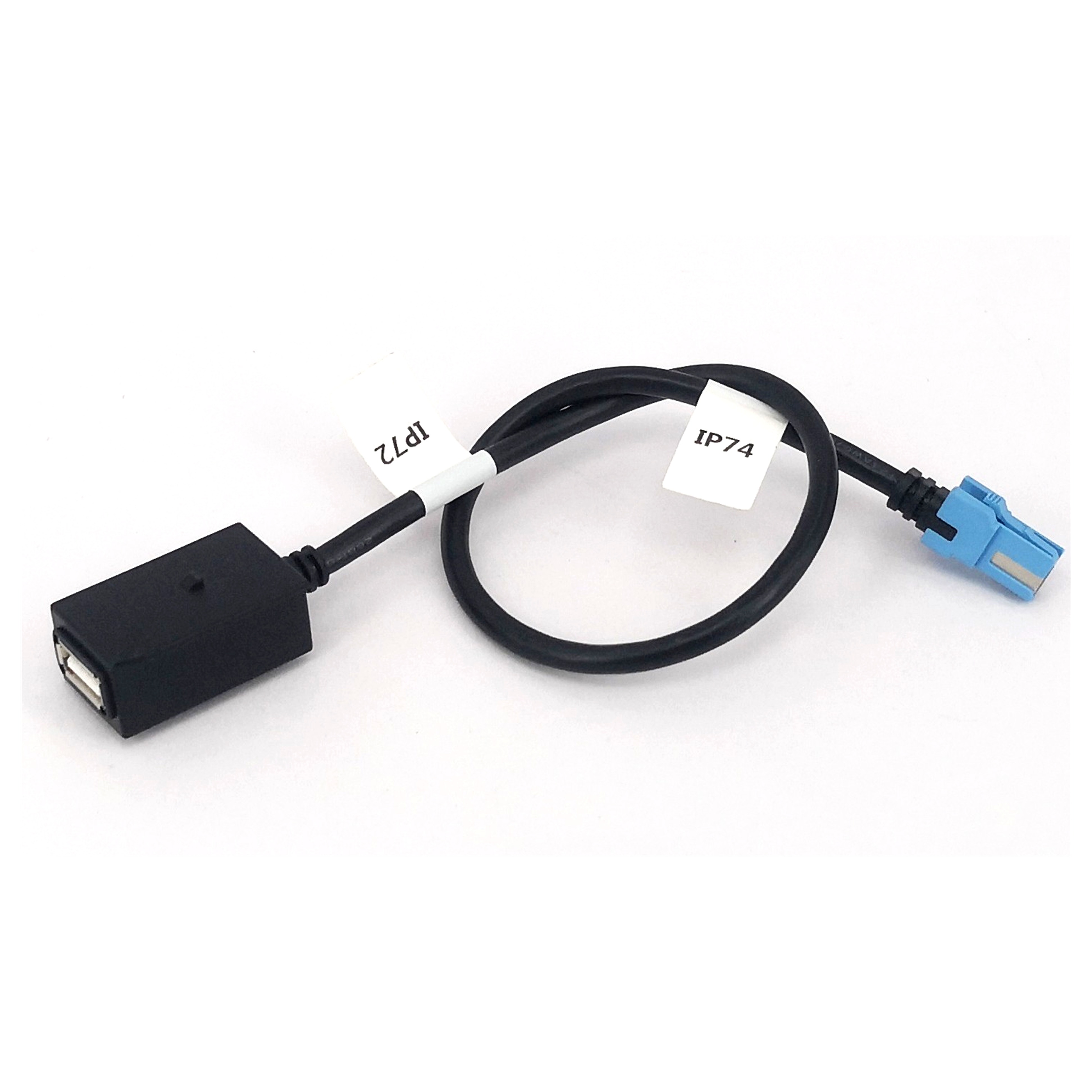
3. Cable Selection: 0.81 mm vs. 1.13 mm vs. 1.37 mm
3.1 The TradeOff Triangle
The coaxial cable between the MHF4 plug and the SMA jack is not a trivial component. Three factors exist in permanent tension: flexibility, loss, and mechanical durability. A thinner cable is more flexible and easier to route through tight spaces, but it exhibits higher attenuation per unit length. A thicker cable reduces loss but is stiffer and requires more generous bend radii. The standard cable sizes for MHF4 assemblies are 0.81 mm, 1.13 mm, and 1.37 mm outer diameter.
The 0.81 mm cable is the default for MHF4 because it matches the connector’s intended application space: ultracompact devices where every millimeter of clearance matters. It is the cable used in standard 100 mm assemblies from Linx, Pulse, and Taoglas. Its attenuation is approximately 2.2 dB per meter at 1 GHz, rising to 5.5 dB per meter at 6 GHz for a typical 1.13 mm cable; the 0.81 mm cable will show slightly higher figures due to its smaller conductor crosssection. For short runs under 150 mm, the absolute loss difference between cable sizes is small—often a fraction of a decibel—and the flexibility advantage of 0.81 mm cable usually outweighs the marginal loss penalty.
The 1.13 mm cable becomes attractive when the assembly length exceeds roughly 200 mm or when the cable must be routed through an environment with significant electromagnetic interference. Its larger shield and dielectric crosssection provide better shielding effectiveness and lower loss. Many IP67rated assemblies specify 1.13 mm cable because the additional mechanical robustness aligns with the environmental sealing requirement. The 1.37 mm cable, used with the MHF4L and MHF4L LK variants, is the thickest option and is reserved for longer runs or applications where the cable may be subject to abrasion or flexing over a larger bend radius.
3.2 Insertion Loss and VSWR Performance
A representative MHF4toSMA assembly using 0.81 mm cable and measuring 100 mm in length exhibits a typical insertion loss of 0.9 dB across DC to 6 GHz. This figure includes the loss contributions of both connectors and the cable. For comparison, the cable alone at 100 mm and 6 GHz contributes approximately 0.55 dB (based on 5.5 dB/m attenuation), meaning the two connectors together add roughly 0.35 dB. This distribution is typical for microcoaxial assemblies and underscores why connector quality matters as much as cable quality in short assemblies.
VSWR performance for MHF4toSMA assemblies is generally specified as ≤ 1.3:1 up to 3 GHz and ≤ 1.5:1 up to 6 GHz. These figures are consistent with the MHF4 connector’s own VSWR rating and represent a level of impedance matching sufficient for most commercial wireless applications. For sensitive receive chains or highorder modulation schemes such as 256QAM in WiFi 6, a VSWR of 1.5:1 corresponds to a return loss of approximately 14 dB, which is adequate but not exceptional. Engineers designing systems where every fraction of a decibel of link margin counts should verify the actual VSWR of the specific assembly rather than relying on a generic specification.
4. Applications Across Wireless Ecosystems
4.1 WiFi and WLAN Systems
The most immediate application for MHF4toSMA assemblies is in WiFi and WLAN equipment. M.2 formfactor WiFi cards—the standard for laptops, miniPCs, and embedded systems—routinely use MHF4 connectors for their antenna ports. The Intel AX210, for example, uses IPEX MHF4 connectors, not U.FL. A short MHF4toSMA bulkhead assembly allows the card’s antenna signals to be brought out to external antennas mounted on the enclosure or, in the case of access points, to distributed antenna systems. In WiFi 6E systems operating in the 6 GHz band, the MHF4 interface’s 6 GHz rating is adequate, though VSWR rises at the band edge.
4.2 Cellular IoT and 5G Sub6 GHz
Cellular IoT modules in LTEM, NBIoT, and 5G sub6 GHz categories present a different set of requirements. These modules often use MHF4 connectors for their main and diversity antenna ports, and the assemblies must handle transmit power levels that, while modest (typically 23 dBm or 200 mW), still demand reliable impedance matching to avoid power reflected back into the module’s PA. The MHF4toSMA assembly provides the bridge between the module’s boardlevel connector and an external cellular antenna, which may be a blade antenna on a vehicle, a ceilingmounted puck antenna in a building, or a stub antenna on a remote sensor enclosure. Taoglas, Pulse, and Quectel all offer MHF4toSMA assemblies specifically characterized for LTE and 5G sub6 GHz applications.
4.3 GNSS and GPS
GNSS receivers are among the most losssensitive RF systems in common use. A GPS signal arriving at the antenna may be as weak as −130 dBm, and every decibel of loss between the antenna and the receiver’s frontend directly degrades positioning accuracy and timetofirstfix. MHF4toSMA assemblies used in GNSS applications are typically kept as short as mechanically feasible—often 50 mm to 100 mm—and may specify 1.13 mm cable even at these short lengths to minimize loss. The SMA end connects to an active GPS antenna, which incorporates a lownoise amplifier (LNA) powered by a DC bias injected on the coaxial line. The assembly’s DC continuity and voltage rating (AC 60 V for MHF4, comfortably above the 3.3 V or 5 V bias used by most active antennas) are therefore important specifications.
4.4 Test and Measurement
In laboratory and production test environments, MHF4toSMA assemblies serve as probe cables. A test engineer may need to inject a signal from a vector network analyzer or signal generator into an MHF4equipped device under test. A highquality MHF4toSMA assembly with known insertion loss and VSWR characteristics allows the engineer to deembed the cable’s contribution from the measurement, isolating the performance of the device itself. For this application, IPEX offers specialized SMA adapters and test boards that provide a controlled, repeatable interface. The standard MHF4’s 30cycle durability rating is a limitation in test environments, where hundreds or thousands of mates may be required; the MHF4L LK or highcycle adapters are preferred in such cases.
4.5 Automotive and Industrial
Automotive telematics, fleet tracking devices, and industrial IoT gateways often operate in environments where vibration, temperature cycling, and moisture are constant threats. The combination of MHF4 on the board side and IP67 SMA on the enclosure side is a common architecture for these systems. The MHF4L LK’s locking mechanism provides additional retention security against vibration, while the IP67 SMA bulkhead prevents water ingress at the external interface. Siretta’s ASMGALxxxXC137S11 series, for example, pairs an MHF4L LK plug with an IP67 SMA female rearmount bulkhead and 1.37 mm cable, targeting exactly this application space.
5. Selection Guide: Matching the Assembly to the Application
5.1 Defining the Interface Requirements
The first step in selecting an MHF4toSMA assembly is to confirm the boardside interface. The presence of a connector that looks like a small RF connector is insufficient information. MHF4, MHF4L, MHF1, MHF2, MHF3, U.FL, W.FL, and various proprietary microcoaxial interfaces exist in overlapping physical envelopes but are not universally interchangeable. The board’s schematic or the module datasheet should specify the exact connector series. If the module uses MHF4, then only an MHF4 or MHF4L plug will mate correctly.
On the SMA side, the key decisions are gender (male or female), mounting style (bulkhead, panelmount, or freehanging), orientation (straight or rightangle), and environmental rating (standard or IP67). SMA gender conventions can be confusing: the “male” connector has the threaded coupling nut and a center pin, while the “female” has the threaded body and a center receptacle. In bulkhead applications, the SMA female jack is the more common choice because it presents a rugged, pinprotected interface to the outside world.
5.2 Length and Routing Considerations
Cable length should be the shortest length that accommodates the mechanical routing requirements. Every additional centimeter of cable adds loss and introduces another variable in the impedance profile. For assemblies under 100 mm, the choice of cable diameter has minimal impact on loss; the flexibility of 0.81 mm cable generally makes it the preferred option. For assemblies from 100 mm to 300 mm, 1.13 mm cable offers a better balance of loss and flexibility. Beyond 300 mm, 1.37 mm cable becomes increasingly attractive, though the MHF4L LK plug is required to accommodate it.
Bend radius is a critical but often overlooked specification. The 0.81 mm cable used with standard MHF4 assemblies has a minimum static bend radius of approximately 3 mm. Violating this radius—by routing the cable around a sharp PCB edge, for example—can deform the dielectric, alter the impedance, and increase VSWR. In compact enclosures, rightangle SMA connectors and careful cable routing are essential to maintain the minimum bend radius.
5.3 Environmental and Durability Requirements
The standard MHF4 connector’s 30cycle durability is adequate for assemblies that will be mated once during device assembly and never disconnected in the field. However, applications that involve field replacement of antennas, repeated testing, or vibration exposure require either the MHF4L LK locking variant or a design that places the mating interface at the SMA end, where the threaded coupling is inherently more robust and the MHF4 connection remains undisturbed.
IP rating is the other environmental consideration. An IP67 rating is meaningless if only the SMA end is sealed and the MHF4 end is exposed to the same environment. In practice, IP67 MHF4toSMA assemblies are used in enclosures that provide sealing around the cable entry, with the MHF4 end remaining inside the protected volume. The IP67 rating on the SMA bulkhead protects the external interface, while the enclosure protects the internal MHF4 connection.
6. Manufacturing and Quality Considerations
6.1 Assembly Process and Consistency
Producing a reliable MHF4toSMA assembly requires more than soldering a cable between two connectors. The center conductor must be terminated with precise geometry to maintain 50 Ω impedance through the transition. The shield must be terminated with low resistance to preserve shielding effectiveness. The cable must be cut to length with tight tolerance, because length variation translates directly into phase variation in applications where multiple assemblies are used in a phased array or diversity configuration.
IPEX’s iFit termination technology addresses some of these challenges by providing a controlled, solderless termination process for the MHF4 end. On the SMA end, the cable is typically soldered or crimped to the connector’s center pin and shield, with the quality of this termination depending on the assembler’s process control. For OEM procurement, the key quality metrics are insertion loss consistency (unittounit variation), VSWR across the specified band, and pull strength at both connector interfaces.
6.2 Testing and Verification
A production MHF4toSMA assembly should be tested for at least three parameters: continuity (center conductor and shield), insertion loss at one or more frequencies, and VSWR. Insertion loss can be measured with a simple power meter and signal generator, while VSWR requires a return loss bridge or vector network analyzer. For highvolume procurement, statistical process control on insertion loss is more practical than 100% VSWR testing, provided the assembly design has been validated during qualification.
7. Market Landscape and Availability
The MHF4toSMA cable assembly market is served by a mix of connector manufacturers, cable assembly specialists, and distributors. IPEX provides the MHF4 connector and a range of SMA adapters and test boards, but the finished cable assemblies are typically produced by third parties under license or using purchased IPEX components. Siretta, Taoglas, Pulse Electronics, Linx Technologies (TE Connectivity), Amphenol RF, Molex, and Quectel all offer catalog MHF4toSMA assemblies in standard lengths from 30 mm to 300 mm, with options for IP67 sealing, rightangle SMA, and locking MHF4 variants.
For custom requirements—nonstandard lengths, specific cable colors, or unique mounting configurations—specialty assembly houses offer buildtoprint services. The lead time for custom assemblies is typically four to eight weeks, compared with immediate availability for catalog parts. Engineers should therefore consider catalog assemblies first and reserve custom specifications for cases where no standard part fits.
8. Future Outlook
The MHF4 interface is wellpositioned for the next several years of wireless development. Its 6 GHz frequency rating covers the full WiFi 6E band and the sub6 GHz 5G bands that will carry the majority of mobile data traffic through the 2020s. The emergence of WiFi 7, which extends into the 6 GHz band with wider channels, will not exceed MHF4’s frequency capability, though it will place greater demands on VSWR consistency across the band. The MHF4L LK locking variant addresses the durability and vibration concerns that arise in automotive and industrial applications, while the MHF5 connector (rated to higher frequencies) serves millimeterwave and upper midband 5G applications that fall outside MHF4’s scope.
For system designers, the practical implication is straightforward: MHF4toSMA assemblies are a mature, wellsupported solution for bringing boardlevel RF signals to external antennas in compact wireless devices. The key to success lies in specifying the assembly correctly—confirming the MHF4 interface, selecting the appropriate cable diameter and length, and matching the SMA configuration to the enclosure and environmental requirements. When these decisions are made with care, the MHF4toSMA assembly becomes an invisible but indispensable link in the wireless signal chain.
The MHF4 to SMA cable assembly occupies a specific and important niche in RF system design. It bridges the gap between the ultraminiature world of boardlevel microcoaxial connectors and the rugged, standardized world of threaded external interfaces. With a 1.2 mm mated height, DC–6 GHz frequency range, and compatibility with 0.81 mm, 1.13 mm, and 1.37 mm coaxial cables, the MHF4 end addresses the space constraints of modern electronics. The SMA end provides the mechanical robustness, shielding effectiveness, and universal compatibility that external antenna connections demand.
From WiFi modules in laptops to cellular IoT gateways in the field, from GNSS receivers to laboratory test benches, these assemblies enable the signal paths that keep wireless systems connected. Understanding their specifications, selecting the right configuration for each application, and recognizing the tradeoffs between cable size, loss, and flexibility are essential skills for any engineer working with modern RF systems. As wireless technology continues to push into higher frequencies and tighter form factors, the MHF4toSMA assembly will remain a fundamental building block of the connected world.
Lucy Yang | lucy.y@toxutech.com
Dotty Zhao | sales04@toxutech.com
Global Business Director / Sales Team / Global Operations


 En
En Cn
Cn Korean
 Home >