

-
Products -PCBA Manufacturing RF Connectors RF Cable Assemblys Embedded Antennas External Antennas GNSS Positioning Solutions
RF Connectors

RF Cable Assemblys
Embedded Antennas
External Antennas
GNSS Positioning Solutions































 Language


Language


Time:2026-10-15 Views:0
Why Integrated GNSS Antenna PCBA Cable Matters in 2026
Global Navigation Satellite System (GNSS) technology has become the invisible backbone of modern civilization. From the smartphone in your pocket to autonomous tractors in precision agriculture, from fleet management systems to life-saving emergency location services, GNSS enables positioning, navigation, and timing (PNT) with remarkable accuracy. At the heart of every GNSS-enabled device lies a critical component that often goes unnoticed: the integrated GNSS antenna PCBA cable.
This integrated assembly—combining the antenna element, printed circuit board assembly (PCBA), and coaxial cable—determines whether your device achieves centimeter-level precision or frustrating signal dropouts. As the GNSS antenna market expands toward an estimated USD 4–6 billion by 2026, understanding the technical intricacies of these integrated solutions has never been more important for engineers, procurement specialists, and product managers.
This comprehensive guide explores every aspect of integrated GNSS antenna PCBA cable assemblies: how they work, how to select the right components, how to install them for optimal performance, and what market trends will shape the industry through 2035.
Understanding Integrated GNSS Antenna PCBA Cable Assemblies
What Is an Integrated GNSS Antenna PCBA Cable?
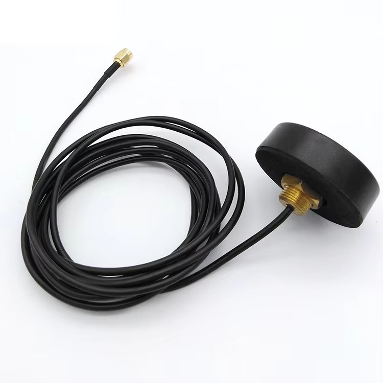
An integrated GNSS antenna PCBA cable assembly is a complete RF front-end solution that combines four essential elements into a single, tested unit:
1. The antenna element — typically a ceramic patch, helical, or PCB trace antenna that captures satellite signals
2. The PCBA — a printed circuit board assembly housing the low-noise amplifier (LNA), filters, and impedance matching components
3. The coaxial cable — a controlled-impedance transmission line carrying the amplified signal to the receiver
4. The connectors — RF interfaces at both ends (antenna-side and receiver-side) that maintain signal integrity
Unlike discrete components purchased separately, an integrated assembly is pre-tuned, pre-tested, and ready for direct integration into your device enclosure. This approach reduces integration risk, shortens development cycles, and ensures consistent RF performance across production batches.
The Role of PCBA in GNSS Antenna Design
The PCBA serves as the electronic brain of the antenna assembly. Modern dual-frequency patch antennas can be entirely formed using standard PCBA processes, including conductive layer etching, dielectric layer stacking, and surface-mount component placement. This manufacturing approach enables:
Precise impedance matching between the antenna element and the LNA
Integrated filtering to reject out-of-band interference
Compact form factors suitable for space-constrained devices
Cost-effective mass production using established PCB fabrication techniques
Electronic components, including RF outputs, are mounted on the routing and placement layer using known PCBA surface-mount processes, ensuring repeatable performance and reliability.
The Anatomy of an Integrated GNSS Antenna Assembly
Antenna Elements: Patch, Helical, and PCB Trace
The antenna element is the first point of contact between your device and the satellite constellation. Three primary technologies dominate integrated GNSS antenna designs:
Ceramic Patch Antennas
Ceramic patch antennas are the most common solution for embedded GNSS applications. They offer a compact footprint, excellent gain at zenith angles, and straightforward surface-mount integration. Amphenol RF's embedded GNSS antennas, for example, are designed for use inside connected devices and can be surface-mounted to a PCB or connectorized for better positioning.
Key characteristics of ceramic patch antennas include:
Right-hand circular polarization (RHCP) for optimal satellite signal reception
Compact dimensions, often 15mm to 25mm square
High dielectric constant ceramics enabling miniaturization
Sensitivity to ground plane size and placement
Helical Antennas
Helical antennas provide broader beamwidth and better performance at low elevation angles compared to patch antennas. They are commonly used in handheld devices and applications where the antenna orientation is unpredictable. However, their larger physical size makes them less suitable for ultra-compact designs.
PCB Trace Antennas
For cost-sensitive applications, PCB trace antennas offer a compelling alternative. These antennas are etched directly onto the main PCB, eliminating the need for a separate antenna component. However, they require careful ground plane design and are more susceptible to detuning from nearby components and enclosure materials.
Low-Noise Amplifier (LNA) and Active Circuitry
GNSS signals arriving at the Earth's surface are extraordinarily weak—typically around -130 dBm. Without amplification, these signals would be lost in the thermal noise floor of the receiver. The LNA is the critical first stage that boosts signal strength without adding excessive noise.
Typical LNA specifications for GNSS applications include:
Gain: 20–30 dB (Cisco's IW-ANT-GNSS-SMA provides 26 dB ± 2 dB)
Noise Figure: Less than 2 dB (some designs achieve 1.4 dB)
Input/Output Impedance: 50 ohms
Current Consumption: Typically 5–15 mA
A two-stage LNA configuration can achieve over 27 dB of gain with a noise figure below 1.4 dB, implemented in the bottom layer of a three-layer antenna package. This level of integration demonstrates how modern PCBA technology enables sophisticated RF front-ends in miniature form factors.
Gain Budget Considerations
For optimum GNSS tracking and TerraStar L-band reception, a cascaded antenna gain of +25 dB to +35 dB is recommended. The total gain budget must account for:
Antenna element gain (typically 2–5 dBic for patch antennas)
LNA gain (20–30 dB)
Cable loss (varies with length and cable type)
Connector losses (0.1–0.5 dB per connection)
Coaxial Cable: The Signal Highway
The coaxial cable connecting the antenna assembly to the receiver is far more than a passive wire. It is a precision transmission line that must maintain 50-ohm impedance, minimize signal loss, and withstand environmental stresses.
Cable Selection Criteria
The quality of antenna cables is categorized by their rated signal loss per meter. Higher-grade cables have less signal loss per linear meter at the expense of increased cost and decreased flexibility.
For GNSS applications, the industry recommends:
Loss < 0.2 dB/m at the L1 frequency (1575.42 MHz) for high-quality installations
Maximum total line loss not exceeding 10.0 dB
50-ohm impedance matching between antenna and receiver
Common Coaxial Cable Types
| Cable Type | Loss at 1.5 GHz (dB/10m) | Typical Application |
|---|---|---|
| RG-58 | ~3.0 dB | Short runs, prototyping |
| RG-174 | ~4.5 dB | Very short runs, internal wiring |
| LMR-240 | ~1.5 dB | Medium runs, mobile installations |
| LMR-400 | ~0.8 dB | Long runs, permanent installations |
| LMR-600 | ~0.5 dB | Very long runs, base stations |
For long-distance transmission exceeding 20 meters, low-loss cables such as LMR-400 or LMR-600 must be selected. Each connection along a cable increases signal loss and adds a potential point of failure.
Cable Length Optimization
The cable should be kept as short as possible to minimize attenuation of the signal. However, practical installation constraints often require longer runs. In such cases, using higher-rated low-loss cable is preferable to adding inline amplifiers, which introduce additional failure points.
RF Connectors: The Critical Interface
Connectors are often the weakest link in an RF chain. A poorly selected or improperly mated connector can introduce significant signal loss, impedance mismatches, and reliability issues.
Housing Connectors vs. Board Connectors
GNSS connectors are divided into two categories:
Housing connectors (BNC, TNC, SMA) — mounted on the receiver or antenna housing, designed for repeated mating cycles
Board connectors (MCX, MMCX, IPEX/U.FL) — mounted directly on the PCB, typically rated for only about ten mating cycles
For stationary installations requiring frequent testing, TNC connectors with thick, low-loss coaxial cables are recommended. For applications requiring occasional antenna changes with cables of 1–2 meters, SMA connectors provide an excellent balance of performance and convenience.
Connector Selection Matrix
| Connector | Impedance | Frequency Range | Mating Cycles | Best For |
|---|---|---|---|---|
| SMA | 50Ω | DC–18 GHz | 500+ | General purpose |
| TNC | 50Ω | DC–11 GHz | 500+ | Vibration environments |
| MCX | 50Ω | DC–6 GHz | ~10 | Compact devices |
| MMCX | 50Ω | DC–6 GHz | ~10 | Ultra-compact devices |
| IPEX/U.FL | 50Ω | DC–6 GHz | ~10 | Internal PCB connections |
When selecting a connector, compatibility with both the impedance and the diameter of the coaxial cable is essential. Otherwise, significant losses will occur in the connector itself.
Design and Integration Best Practices
PCB Layout Guidelines for GNSS Antennas
Successful GNSS antenna integration begins at the PCB layout stage. Key considerations include:
Ground Plane Design
The ground plane beneath a patch antenna acts as a reflector, shaping the radiation pattern and improving gain. The minimum recommended ground plane radius is 60 mm for optimal performance. For u-blox SAM-M8Q modules, a 50 × 50 mm ground plane is recommended, though larger or smaller ground planes can be used with performance trade-offs.
Antenna Placement
The antenna should be placed at the edge or corner of the PCB, away from:
High-speed digital traces that can radiate interference
Power supply switching regulators
Metal components that can detune the antenna
Display panels and other noise sources
Impedance Matching
A matching network (typically consisting of capacitors and inductors) is essential to compensate for component tolerances and environmental detuning. The matching network should be tuned with the antenna installed in its final enclosure, as nearby materials significantly affect antenna impedance.
Active Antenna Power Supply Design
Active GNSS antennas require DC power to operate the LNA, typically fed through the coaxial cable using a bias tee. The bias tee consists of:
An inductor (RFC) to isolate the DC supply from the RF path
A capacitor to block DC from reaching the receiver input
Overcurrent protection to prevent damage from short circuits
The DC voltage is typically 3.3V or 5V, with current consumption ranging from 5 mA to 30 mA depending on the LNA design.
Enclosure and Environmental Considerations
The antenna assembly must be protected from environmental hazards:
IP-rated enclosures for outdoor installations
UV-stabilized materials for prolonged sun exposure
Self-amalgamating tape for sealing cable connections against water infiltration
Strain relief to prevent tension on cable connections
Installation and Deployment Guide
Outdoor Installation: Base Stations and Permanent Mounts
For permanent GNSS installations such as CORS (Continuously Operating Reference Station) networks, the following practices are essential:
Site Selection
Choose an open, unobstructed location away from tall buildings, metal structures, trees, and water surfaces. The ideal position is on a building rooftop or in the center of an open field.
Mounting Height
Antenna height should be at least 2–3 meters above the ground or nearby reflecting surfaces. For high-precision applications, mounting on a tower or elevated mast is recommended.
Multipath Mitigation
Multipath effects—where signals reflect off surfaces before reaching the antenna—are the enemy of GNSS accuracy. Mitigation strategies include:
Using a choke ring antenna to suppress low-angle reflected signals
Installing a large metal reflector plate beneath the antenna
Ensuring vertical mounting (even slight tilts increase multipath susceptibility)
Orienting the antenna away from known strong reflectors
Cable Protection
Externally running cables should be protected using buried or secured conduits. Dedicated cableways are recommended within buildings. Cable connectors should be sealed with self-amalgamating UV-stabilized tape.
Lightning Protection
Include a grounded lightning protector on the antenna cable. In lightning-prone areas, reduce horizontal cable-run length to minimize the risk of signal induction from nearby strikes.
Vehicle and Mobile Installations
For automotive and mobile applications, installation considerations shift:
Roof mounting is typically best, as windows and other obstructions won't interfere with signals
Center placement on the vehicle roof minimizes multipath asymmetry
Level mounting ensures consistent satellite tracking
Low-loss cable (LMR-240 or better) should be used for runs from roof to dashboard
Keep clear of cellular, Wi-Fi, and DSRC antennas to avoid interference
For vehicle installations, the unit should be positioned as close to the center of the vehicle as possible and level with the ground.
IoT and Embedded Device Integration
In compact IoT devices, every millimeter counts. Integrated GNSS antenna PCBA cable assemblies offer significant advantages:
Pre-tuned assemblies eliminate the need for in-house RF expertise
Flexible cable options (1.13mm, 1.37mm) allow routing through tight enclosures
U.FL/IPEX connectors enable modular assembly and field replacement
Surface-mount ceramic antennas support automated PCB assembly
Market Trends and Future Outlook (2026–2035)
Market Size and Growth Projections
The global GNSS antenna market is experiencing robust growth driven by multiple converging trends:
The global GNSS antenna and GPS antenna market was estimated at USD 5,320 million in 2025, projected to grow at a CAGR of 4.60%
The high-precision GNSS antenna segment alone was valued at USD 1,426.61 million in 2025, with a projected CAGR of 6.40%
The external GNSS active antenna market is forecast to grow from USD 224 million in 2025 to USD 285 million by 2032, at a CAGR of 3.2%
Global unit volumes of GNSS antennas are expected to approximately double over the 2026–2035 period, representing high single-digit compound annual growth
Key Market Trends
Multi-Band, Multi-Constellation Antennas
Multi-band, multi-constellation (GPS, GLONASS, BeiDou, Galileo) antennas are becoming baseline requirements, pushing premium segments to grow 2–3% per year faster than single-band segments. This trend is driven by the need for improved accuracy, faster time-to-first-fix, and resilience against signal degradation in urban canyons.
Antenna-in-Package (AiP) Integration
The integration of active antennas with receiver modules and antenna-in-package designs for miniaturized UAVs and wearables is reducing discrete component procurement while raising average unit value for advanced modules. This trend favors integrated PCBA cable assemblies that combine multiple functions into a single tested unit.
Regulatory Drivers
Regulatory mandates for emergency location accuracy (FCC, E112) and autonomous safety-of-life certification (ISO 26262, SIL) are shifting procurement toward validated, traceable suppliers rather than open-market component distributors. This increases demand for integrated assemblies with documented performance and reliability data.
Geographic Production Shifts
Supply remains heavily concentrated in East Asian manufacturing hubs, with China accounting for an estimated 55–65% of global production. However, assembly and testing capacity is rising in North America and Europe for defense-aerospace and sensitive infrastructure procurement.
Challenges Facing the Industry
Input Cost Volatility
Rare-earth oxides for low-noise amplifiers and copper-clad laminates create 15–30% swings in bill-of-materials costs within a single contract year, pressuring contract pricing and margin predictability.
Supplier Qualification Cycles
In aerospace, defense, and railway applications, supplier qualification cycles can exceed 18 months, limiting the speed at which new capacity can address demand spikes for high-reliability grades.
Geopolitical Trade Restrictions
Trade restrictions on electronics components—especially chipsets and multi-GNSS modules with encryption functions—are forcing dual-supply strategies and increasing logistics costs for cross-border shipments.
Content Structure for Maximum Engagement
High-ranking technical content follows a predictable structure:
1. Introduction — Establish the problem and promise a solution
2. Technical Foundation — Explain the underlying technology clearly
3. Practical Guidance — Provide actionable selection and installation advice
4. Market Context — Connect technical decisions to business outcomes
5. Conclusion — Summarize key takeaways and include a call to action
The integrated GNSS antenna PCBA cable is far more than a commodity component. It is a precision-engineered RF system that determines the positioning accuracy, reliability, and time-to-market of your GNSS-enabled product. From ceramic patch antenna selection to LNA gain budgeting, from coaxial cable loss calculations to connector mating cycle ratings, every decision in the design chain influences end-user experience.
As the GNSS antenna market accelerates toward new highs in 2026 and beyond—driven by autonomous vehicles, precision agriculture, IoT expansion, and regulatory mandates—choosing an experienced integration partner becomes a strategic advantage. Look for suppliers who can provide:
Complete PCBA antenna integration with documented RF performance
Multi-band, multi-constellation support for future-proof designs
Custom cable lengths and connector options for your specific enclosure
Design support services including PCB layout review and tuning
Production testing with traceable data for regulatory compliance
Whether you are developing a fleet management system, an autonomous drone, a precision surveying instrument, or a next-generation IoT tracker, the right integrated GNSS antenna PCBA cable assembly will deliver the signal integrity your application demands—and the market differentiation your business needs.
Author Bio: [Your Company Name] specializes in RF hardware development, including GNSS antennas, communication antennas, RF cable assemblies, and integrated PCBA solutions for IoT devices, vehicle electronics, industrial communication, and smart infrastructure applications. Contact us to discuss your integrated GNSS antenna requirements.
Lucy Yang | lucy.y@toxutech.com
Dotty Zhao | sales04@toxutech.com
Global Business Director / Sales Team / Global Operations


 En
En Cn
Cn Korean
 Home >