

-
Products -PCBA Manufacturing RF Connectors RF Cable Assemblys Embedded Antennas External Antennas GNSS Positioning Solutions
RF Connectors

RF Cable Assemblys
Embedded Antennas
External Antennas
GNSS Positioning Solutions































 Language


Language


Time:2026-10-15 Views:0
In the rapidly evolving world of wireless communication, satellite navigation, and radar systems, the demand for antennas that deliver both high gain and circular polarization has never been greater. Among the many antenna configurations available to RF engineers, the high gain four arm helical antenna—also known as the quadrifilar helix antenna (QHA)—stands out as a remarkably versatile and high-performance solution. Originally pioneered by C.C. Kilgus in 1968, this antenna architecture has become a cornerstone technology in satellite communication, global navigation satellite systems (GNSS), and advanced radar applications.
The four arm helical antenna is distinguished by its unique ability to produce circularly polarized radiation with a cardioid-shaped pattern, offering wide beam coverage and excellent axial ratio performance. When optimized for high gain, this antenna becomes an indispensable component in systems where signal integrity, polarization purity, and directional coverage are paramount. This comprehensive guide explores every aspect of the high gain four arm helical antenna, from fundamental operating principles to cutting-edge design optimization techniques, applications, and future trends.
Whether you are an RF engineer designing satellite communication systems, a researcher exploring advanced antenna topologies, or a technical professional seeking to understand the capabilities of quadrifilar helix antennas, this article provides the depth and breadth of information you need.
What Is a Four Arm Helical Antenna?
Fundamental Architecture
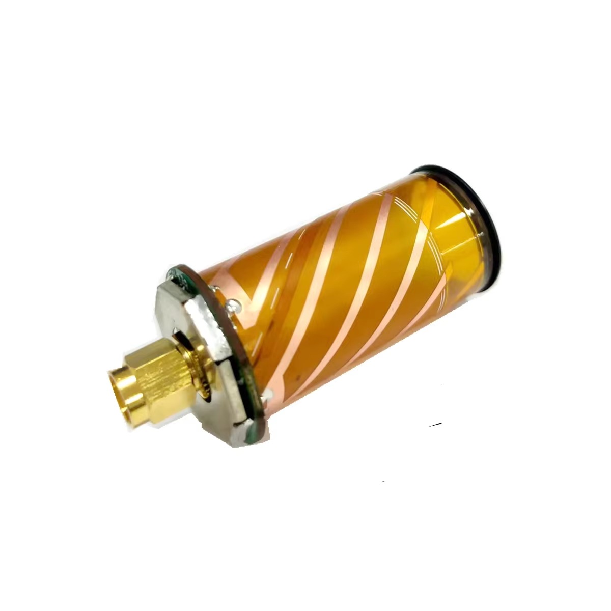
A four arm helical antenna is a circularly polarized antenna consisting of four conductive arms (also called filars or helices) wound around a common cylindrical or conical support structure. Unlike a conventional single-arm helix antenna, which operates in axial mode with a directional end-fire radiation pattern, the four arm helical antenna typically operates in a normal mode or backfire mode, producing a broad hemispherical or cardioid radiation pattern.
The four arms are typically arranged in a rotational symmetry about the central axis, with each arm being fed with a signal of equal amplitude but with progressive phase shifts of 0°, 90°, 180°, and 270°. This quadrature feeding arrangement is what generates the circular polarization and the characteristic wide-beam radiation pattern.
Key Design Parameters
The performance of a four arm helical antenna is governed by several critical geometrical and electrical parameters:
Number of turns (N): Determines the electrical length of the antenna and influences gain and bandwidth.
Helix diameter (D): The diameter of the cylindrical volume around which the arms are wound.
Pitch angle (α): The angle between the helix winding and the plane perpendicular to the axis.
Axial length (L): The total height of the helical structure.
Arm width: The width of each conductive strip or wire.
Ground plane geometry: The size and shape of the ground plane or reflector, which significantly affects gain and front-to-back ratio.
The Quadrifilar Helix Advantage
The quadrifilar helix configuration offers several inherent advantages over other circularly polarized antennas:
1. Excellent circular polarization purity: The four-arm feeding scheme naturally produces high-quality circular polarization with low axial ratio across a wide angular range.
2. Wide beam coverage: The antenna provides a hemispherical or cardioid radiation pattern that is ideal for satellite communication, where satellites may be at various elevation angles.
3. Compact form factor: Unlike planar microstrip antennas that require large substrates, the four arm helix can achieve comparable performance in a compact cylindrical volume.
4. Design flexibility: The antenna can be optimized for different frequency bands, gain levels, and beam shapes by adjusting its geometrical parameters.
Operating Principles of the High Gain Four Arm Helical Antenna
Circular Polarization Generation
The generation of circular polarization in a four arm helical antenna is rooted in the phase relationship between the four arms. When the four arms are fed with signals that are 90° out of phase in sequence (0°, 90°, 180°, 270°), the resulting electromagnetic fields combine to produce a rotating electric field vector—the hallmark of circular polarization.
The direction of circular polarization (right-hand or left-hand) is determined by the phase progression sequence. A 0°→90°→180°→270° progression generates right-hand circular polarization (RHCP), while the reverse progression generates left-hand circular polarization (LHCP). This polarization agility makes the four arm helix particularly attractive for dual-polarized systems and polarization diversity applications.
Radiation Pattern and Gain
The radiation pattern of a four arm helical antenna in its normal operating mode resembles a cardioid or hemispherical shape, with maximum radiation along the axis of the helix. The gain of the antenna is influenced by several factors:
Axial length: Longer antennas generally exhibit higher gain, but with diminishing returns beyond a certain length.
Ground plane size and shape: A properly designed ground plane can significantly enhance gain by reflecting back radiation and shaping the pattern.
Dielectric loading: The introduction of dielectric materials within the helix can alter the effective wavelength and affect gain characteristics.
Array configuration: Multiple four arm helical elements can be combined into arrays to achieve gains of 20 dBi or more.
Feed Network Design
The feed network is perhaps the most critical component in a high gain four arm helical antenna system. The feed network must divide the input signal into four equal-amplitude outputs with precise 90° phase differences across the operating frequency band.
Common feed network topologies include:
Microstrip power dividers: Compact and planar, suitable for integration with printed circuit board (PCB) antennas.
Lange couplers: Provide broadband quadrature phase shift with excellent amplitude balance.
Balun-based feeds: Use balanced-to-unbalanced transformers to achieve the required phase relationships.
Integrated LTCC feed networks: Low-temperature co-fired ceramic (LTCC) technology enables compact, multi-layer feed networks with excellent performance at millimeter-wave frequencies.
The quality of the feed network directly impacts the antenna's axial ratio, impedance matching, and overall efficiency. Poor feed network design can degrade circular polarization purity and reduce gain, even if the radiating structure itself is well-designed.
Design Strategies for High Gain Performance
Achieving high gain in a four arm helical antenna requires careful attention to multiple design parameters. Several proven strategies can be employed to maximize gain while maintaining excellent circular polarization characteristics.
Ground Plane Optimization
The ground plane plays a pivotal role in determining the gain and radiation characteristics of a four arm helical antenna. Research has demonstrated that shaping the ground conductor can significantly enhance gain and improve radiation characteristics.
A truncated-cone reflector has been shown to be particularly effective. Studies comparing different ground plane geometries found that a truncated-cone reflector can significantly increase the gain of a helical antenna compared to a circular or square flat reflector. The optimal design of the truncated horn is typically obtained through optimization algorithms such as genetic algorithms (GA) or particle swarm optimization (PSO).
For instance, a high-gain quad array of helical antennas placed inside a truncated horn ground plane achieved a gain of approximately 19.6 dBi, which is more than 3 dBi higher than a similar array using a square ground plane.
Dielectric Loading and Miniaturization
While high gain often correlates with larger antenna dimensions, there are applications where compact size is equally important. Dielectric loading involves inserting a dielectric material (such as a ceramic rod or cylinder) within the helical volume. This technique effectively reduces the physical size of the antenna while maintaining its electrical performance.
A hollow ceramic rod used as a dielectric load can reduce the antenna size to only 2.7% of an air-loaded quadrifilar helix antenna. However, it is important to note that miniaturization can affect efficiency and gain. Research has shown that efficiency and gain do not decrease linearly with the reduction of antenna height, and input matching may even improve for compact antennas.
Array Configurations
For applications requiring gains exceeding 15 dBi, a single four arm helical element may not be sufficient. Array configurations—where multiple four arm helical elements are combined—can achieve significantly higher gains.
A four-element collinear dual-polarized array has been demonstrated to achieve peak realized gain values of 7.55 and 7.26 dBic for RHCP and LHCP, respectively, with excellent isolation greater than 25 dB between polarizations. For even higher gains, an 8×8 phased array antenna based on LTCC technology achieved a peak realized gain of 21 dBi with a 6 GHz bandwidth (20%) in the 27–33 GHz range.
The key to successful array design lies in proper element spacing, feeding network design, and sequential rotation feeding to maintain axial ratio performance across the scanning range.
Arm Geometry and Tapering
The geometry of the individual helical arms also influences gain performance. Tapered or varying-width arms can be used to control the current distribution along the helix, potentially improving gain and bandwidth. Some advanced designs employ folded arms or arms with gaps to achieve miniaturization while broadening impedance bandwidth.
Additionally, the pitch angle of the helix affects the phase velocity of the traveling wave along the antenna, which in turn influences gain and axial ratio. Optimizing the pitch angle for a given frequency band is essential for maximizing performance.
Applications of High Gain Four Arm Helical Antennas
Satellite Navigation and GNSS
The most widespread application of four arm helical antennas is in satellite navigation systems such as GPS, GLONASS, Galileo, and BeiDou. The antenna's circular polarization, wide beam coverage, and ability to receive signals from satellites at various elevation angles make it ideally suited for this application.
For GNSS reference station antennas, the requirements are particularly demanding: the antenna must have a radiation pattern close to an ideal hemisphere, uniform right-hand circular polarization gain in the upper half-space, and sharp cutoff below 5° elevation to suppress multipath effects. The four arm helical antenna meets these requirements exceptionally well, which is why it is the antenna of choice for high-precision GNSS applications.
Satellite Communication
In satellite communication systems, high gain and circular polarization are essential for maintaining link margins and overcoming atmospheric attenuation. The four arm helical antenna is widely used in handheld satellite phones, mobile satellite terminals, and Earth station antennas.
For handheld satellite transceivers, the antenna must provide a net gain of at least 2 dBi over all elevation angles exceeding 45°, with an axial ratio of less than 3 dB. The compact quadrifilar helix meets these requirements while maintaining a form factor suitable for portable devices.
Radar Systems
The wideband characteristics of the quadrifilar helical antenna make it attractive for radar applications. A C-band QHA designed for wideband radar applications achieved a gain of 5.27 dBi across the 4–8 GHz frequency band, with an omnidirectional radiation pattern suitable for surveillance and detection systems.
Long-Range IoT and LoRa
The Internet of Things (IoT) has created new demands for compact, high-gain antennas for long-range communication. A helix quadrifilar antenna designed for LoRa applications operating at 915 MHz achieved a gain of 7.52 dBi, a return loss of −16.32 dB, and a VSWR of 1.37, with a bandwidth of 32 MHz. The truncated conical ground reflector was instrumental in enhancing the gain of this design.
Direction Finding and RF Monitoring
Four arm spiral antennas, which share many characteristics with the quadrifilar helix, are widely used in direction finding (DF) applications. These include locating threat emitters, jammers, RF search and rescue beacons, tracking animals, and radio monitoring.
Challenges and Limitations
Despite their many advantages, high gain four arm helical antennas present several design and implementation challenges that engineers must address.
Feed Network Complexity
The feed network is often the most challenging aspect of QHA design. Achieving precise 90° phase shifts with equal amplitude across a wide frequency band requires careful design and tight manufacturing tolerances. Any amplitude or phase imbalance directly translates to degraded axial ratio and reduced gain.
Bandwidth Limitations
While four arm helical antennas offer reasonable bandwidth, achieving both high gain and wide bandwidth simultaneously can be challenging. The impedance bandwidth and axial ratio bandwidth may not perfectly overlap, requiring careful optimization to ensure satisfactory performance across the desired frequency range.
Size and Integration
For low-frequency applications (e.g., VHF and UHF bands), the four arm helical antenna can become physically large, making integration into compact devices difficult. Dielectric loading and miniaturization techniques can help, but these approaches may compromise gain and efficiency to some degree.
Thermal Management in High-Power Applications
In high-power transmit applications, the feed network and radiating elements must be designed to handle significant thermal loads. The construction technique must ensure adequate heat dissipation, particularly in phased array configurations where multiple elements are densely packed.
Optimization Techniques and Advanced Design Methods
Modern antenna engineering leverages sophisticated computational and optimization techniques to maximize the performance of four arm helical antennas.
Genetic Algorithms and Evolutionary Optimization
Genetic algorithms (GA) have been successfully applied to optimize the geometry of helical antennas and their ground planes. The optimization goal is typically to maximize antenna gain in the axial direction while maintaining acceptable axial ratio and impedance matching.
GA is particularly useful for optimizing the shape of the ground plane (e.g., truncated horn dimensions) where the relationship between geometry and performance is complex and non-intuitive.
Artificial Intelligence and Machine Learning
Recent research has explored the use of Artificial Intelligence (AI) and machine learning for antenna design optimization. The Grey Wolf Optimizer (GWO), for example, has been employed to efficiently search the design space and identify optimal values for key parameters such as the number of turns, helix pitch, and helix diameter, with the objective of maximizing antenna gain to achieve a target of 15 dBi.
Simulation Tools
Full-wave electromagnetic simulation software such as CST Microwave Studio, HFSS, and FEKO are indispensable tools for QHA design. These tools allow engineers to accurately model the complex interactions between the helical arms, feed network, ground plane, and surrounding environment, enabling rapid design iteration and optimization.
Future Trends and Emerging Technologies
The field of four arm helical antenna design continues to evolve, driven by emerging applications and technological advances.
Millimeter-Wave and 5G/6G Applications
As wireless communication moves toward millimeter-wave frequencies (28 GHz, 38 GHz, and beyond) for 5G and future 6G systems, the four arm helical antenna is being adapted for these bands. LTCC-based phased array antennas with four-arm helical elements have demonstrated excellent performance in the 27–33 GHz range, achieving 21 dBi gain and 20% bandwidth.
Metamaterial and Artificial Surface Integration
The integration of metamaterials and artificial surface plasmon polariton (SSPP) structures with four arm helical antennas opens new possibilities for performance enhancement and miniaturization. These engineered materials can manipulate electromagnetic waves in ways not possible with conventional materials, potentially leading to antennas with unprecedented gain, bandwidth, or compactness.
Dual-Band and Multi-Band Designs
Modern communication systems often require operation across multiple frequency bands. Dual-band and multi-band four arm helical antennas are being developed to serve applications such as combined GPS and satellite communication, or multi-constellation GNSS reception. These designs typically employ folded arms, parasitic elements, or multi-resonant feed networks to achieve multi-band operation.
Additive Manufacturing
3D printing and additive manufacturing technologies are enabling new approaches to fabricating complex helical antenna structures. These techniques allow for precise control over arm geometry, dielectric loading, and integrated feed networks, potentially reducing manufacturing costs and enabling rapid prototyping.
Frequently Asked Questions (FAQ)
What is the difference between a four arm helical antenna and a quadrifilar helix antenna?
They are the same thing. "Four arm helical antenna" and "quadrifilar helix antenna" (QHA) are synonymous terms used interchangeably in the antenna engineering community. Both refer to a circularly polarized antenna with four helical arms fed in quadrature phase.
What is the typical gain of a four arm helical antenna?
A single four arm helical antenna element typically provides a gain in the range of 3 to 8 dBi, depending on its size, ground plane, and design optimization. For higher gains, multiple elements can be combined into arrays, achieving gains of 15 dBi or more.
Can a four arm helical antenna be used for both transmit and receive?
Yes. The four arm helical antenna is a reciprocal device, meaning it can function equally well for both transmission and reception. This makes it ideal for bidirectional communication systems such as satellite transceivers.
What is the axial ratio of a good four arm helical antenna?
A well-designed four arm helical antenna should achieve an axial ratio of less than 3 dB over its intended coverage angle. Some optimized designs achieve axial ratios below 1 dB in the main beam direction.
How can I increase the gain of my quadrifilar helix antenna?
Several approaches can increase gain: optimizing the ground plane geometry (e.g., using a truncated cone reflector), increasing the axial length of the helix, employing dielectric loading, and combining multiple elements into an array configuration.
The high gain four arm helical antenna represents a remarkable achievement in antenna engineering—a design that elegantly balances circular polarization purity, wide beam coverage, and gain performance in a compact, versatile package. From its origins in the late 1960s to its current role in satellite navigation, 5G/6G communication, and advanced radar systems, the quadrifilar helix antenna has proven its enduring value.
As wireless technology continues to advance toward higher frequencies, greater bandwidths, and more demanding performance requirements, the four arm helical antenna will undoubtedly continue to evolve. Emerging techniques such as AI-driven optimization, metamaterial integration, and additive manufacturing are opening new frontiers for this classic antenna architecture, ensuring its relevance for decades to come.
For engineers and researchers working in RF and antenna design, a thorough understanding of the high gain four arm helical antenna—its principles, design parameters, optimization strategies, and applications—is an essential part of the professional toolkit. Whether you are designing a GNSS receiver for autonomous vehicles, a satellite communication terminal for remote areas, or a phased array for next-generation wireless networks, the four arm helical antenna offers a proven, high-performance solution.
Lucy Yang | lucy.y@toxutech.com
Dotty Zhao | sales04@toxutech.com
Global Business Director / Sales Team / Global Operations


 En
En Cn
Cn Korean
 Home >