

-
Products -PCBA Manufacturing RF Connectors RF Cable Assemblys Embedded Antennas External Antennas GNSS Positioning Solutions
RF Connectors

RF Cable Assemblys
Embedded Antennas
External Antennas
GNSS Positioning Solutions































 Language


Language


Time:2026-10-16 Views:0
Why GNSS RF Pigtail Cable Assemblies Matter
In the world of satellite navigation, the difference between a positioning system that works flawlessly and one that struggles with accuracy often comes down to the smallest components. Among these, the GNSS RF pigtail cable assembly plays a role that is both critical and frequently underestimated. A GNSS RF pigtail cable assembly is a short, flexible coaxial cable terminated with connectors at both ends, designed to bridge the gap between a GNSS antenna and a receiver or module. While it may appear to be a simple piece of hardware, its impact on signal integrity, positioning accuracy, and overall system reliability is profound.
GNSS signals arrive at the antenna at extremely low power levels, typically well below the noise floor. This inherent weakness makes GNSS systems far more sensitive to cable loss and connector quality than many other RF applications. Every decibel of insertion loss, every impedance mismatch, and every poorly shielded connector can degrade the signal-to-noise ratio available to the receiver, directly affecting time-to-first-fix, positioning precision, and system stability. For this reason, selecting the right GPS/GNSS RF cable assembly is not merely a mechanical choice — it is a fundamental part of GNSS system design.
This comprehensive guide explores every aspect of GNSS RF pigtail cable assemblies, from the fundamental principles of RF transmission to the practical considerations of cable selection, connector types, environmental protection, and industry standards. Whether you are designing a high-precision surveying system, integrating GNSS into an automotive telematics platform, or building compact IoT devices with positioning capabilities, this article will provide the technical depth and practical insights you need to make informed decisions.
Understanding the Fundamentals of GNSS Signal Transmission
GNSS Frequency Bands and Their Implications
The Global Navigation Satellite System (GNSS) encompasses multiple satellite constellations, including GPS, GLONASS, Galileo, and BeiDou. While each constellation operates with its own specific channel plan, the majority of their civil navigation signals are clustered within a relatively narrow frequency range around 1.1 GHz to 1.6 GHz. The most widely used GPS frequencies include L1 (1575.42 MHz), L2 (1227.60 MHz), and L5 (1176.45 MHz). Among these, L1 is the most commonly supported band in commercial and industrial GNSS receivers, while L2 and L5 are increasingly used in professional and high-precision applications.
This frequency convergence allows a single RF cable assembly to be used across multi-constellation GNSS systems, provided that the cable and connectors maintain stable impedance, consistent shielding effectiveness, and low insertion loss across the entire operating band. For this reason, GNSS cable selection is typically driven more by broadband RF performance and mechanical reliability than by constellation-specific frequency differences.
The Critical Role of Cable Loss
Because GNSS signals are transmitted at very low power levels by satellites and experience significant free-space path loss before reaching the receiving antenna, any additional attenuation introduced by the RF cable assembly directly affects the signal-to-noise ratio available to the receiver. This makes cable loss one of the most important parameters to consider when selecting a GNSS RF pigtail cable assembly.
The IGS (International GNSS Service) guidelines recommend using high-quality low-loss cables with a loss of less than 0.2 dB/m at the L1 frequency. However, in practice, the acceptable loss depends on the specific application. For RTK systems, the total feeder attenuation is generally recommended to be controlled within 3 dB to ensure good reception quality. For standard GNSS receivers, the maximum acceptable cable loss is typically around 10 dB.
Anatomy of a GNSS RF Pigtail Cable Assembly
The Coaxial Cable: The Primary Transmission Medium
The coaxial cable forms the primary transmission medium in a GNSS RF pigtail cable assembly. Its function is to carry extremely low-level GNSS signals from the antenna to the receiver while preserving signal integrity. A typical coaxial cable consists of a center conductor, dielectric insulation, shielding layer, and outer jacket, all designed to maintain controlled impedance and minimize signal loss.
The choice of coaxial cable type is one of the most consequential decisions in specifying a GNSS RF pigtail assembly. Different cable types offer different trade-offs between signal loss, flexibility, durability, and cost. The most commonly used cable types in GNSS applications include:
RG-Series Cables (RG174, RG316, RG58, RG178): RG-series coaxial cables are among the most commonly used cable types in GPS and GNSS systems due to their standardized construction and well-documented performance characteristics. RG174 is a flexible, small-diameter cable (2.79 mm) with an attenuation of approximately 0.97 dB/m at 1 GHz. RG316 offers similar flexibility with slightly better attenuation characteristics at approximately 0.85 dB/m at 1 GHz. RG58 provides a larger diameter (approximately 5 mm) with lower loss, typically around 0.92 dB/m. RG178 is an ultra-miniature cable used in space-constrained applications such as U.FL/IPEX connections.
LMR-Series Cables (LMR-100, LMR-195, LMR-200, LMR-240, LMR-400): LMR (Land Mobile Radio) cables are premium low-loss coaxial cables designed for demanding RF applications. They offer significantly lower attenuation than standard RG cables, making them ideal for longer cable runs. For example, LMR-240 has an attenuation of approximately 0.26 dB/m, while LMR-400 offers even lower loss for extended distances. LMR cables are particularly well-suited for GNSS antenna feeder runs, inter-cabinet jumpers, and GPS system wiring applications.
Specialized Low-Loss Cables: Beyond the standard RG and LMR families, manufacturers offer specialized low-loss cables optimized for GNSS frequencies. These include cables with foam polyethylene dielectric, silver-plated copper conductors, and advanced shielding configurations that minimize signal leakage while maintaining flexibility. The PCTEL PFP195, for instance, is an ideal cable for longer RF cable runs that require high flexibility as well as low signal attenuation, making it suitable for GPS, LMR, WLAN, and SCADA applications.
RF Connectors: The Critical Interface
RF connectors provide the mechanical and electrical interface between the coaxial cable, the GNSS antenna, and the receiver or module. In GPS/GNSS systems, connectors must ensure consistent impedance matching, low insertion loss, and reliable physical retention over the operational lifetime of the system. Commonly used GNSS connector types include SMA, MCX, MMCX, U.FL, and FAKRA, each suited to different installation environments and form-factor constraints.
SMA (SubMiniature version A): The SMA connector is the workhorse of GNSS RF connections. It offers excellent electrical performance up to 18 GHz, a threaded coupling mechanism for secure mating, and a compact form factor. SMA connectors are available in standard polarity and reverse polarity (RP-SMA) configurations, with straight and right-angle geometries. They are rated for 500 mating cycles and provide reliable performance in both indoor and outdoor environments.
FAKRA (Fachkreis Automobil): FAKRA connectors are the standard for automotive GNSS applications. They feature a color-coded, keyed housing that prevents mismating and ensures reliable connection in vehicle environments. FAKRA connectors support frequencies up to 6 GHz and are designed to withstand the vibration, temperature extremes, and repeated flexing encountered in automotive applications. GNSS FAKRA connectors typically use code C (blue) for identification.
U.FL / IPEX (MHF): U.FL and IPEX connectors are ultra-miniature RF connectors designed for space-constrained applications. They are commonly found on GNSS receiver modules, Mini PCIe cards, and embedded systems where board space is at a premium. These connectors support frequencies up to 6 GHz and are typically used with micro-coaxial cables such as 1.13 mm and RG178.
MCX and MMCX: MCX (Micro Coaxial) and MMCX (Micro-Miniature Coaxial) connectors offer snap-on coupling mechanisms for quick installation. They are smaller than SMA connectors and are often used in wireless communication modules, GPS receivers, and portable devices. MMCX connectors are particularly common in applications where space is limited and rapid assembly is required.
TNC and N-Type: TNC (Threaded Neill-Concelman) connectors are threaded versions of BNC connectors, offering superior performance at higher frequencies and in vibration-prone environments. They are commonly used for GNSS antenna connections in outdoor installations. N-Type connectors are larger, weatherproof connectors used for high-power and outdoor applications, capable of withstanding harsh environmental conditions.
Key Performance Specifications for GNSS RF Pigtail Cable Assemblies
Impedance: The Foundation of RF Performance
All GNSS RF pigtail cable assemblies operate at a nominal impedance of 50 ohms. This standardized impedance ensures compatibility between antennas, cables, and receivers from different manufacturers. Impedance mismatches cause signal reflections, which manifest as increased VSWR (Voltage Standing Wave Ratio) and return loss, ultimately degrading the signal reaching the receiver. Maintaining a consistent 50-ohm impedance throughout the entire signal path — from the antenna connector through the cable to the receiver input — is essential for optimal GNSS performance.
Insertion Loss: The Signal Killer
Insertion loss is the reduction in signal power resulting from the insertion of the cable assembly into the transmission path. It is expressed in decibels (dB) and increases with both cable length and frequency. In GNSS applications, insertion loss directly impacts the signal-to-noise ratio and, consequently, positioning accuracy.
For GNSS RF pigtail assemblies, insertion loss specifications typically range from 0.2 dB to 1.0 dB for short assemblies (under 30 cm) using RG174 or RG316 cable. Longer assemblies or those using low-loss cable can maintain lower insertion loss over greater distances. For example, a high-performance assembly might achieve insertion loss as low as 0.00203 dB/mm × A mm + 0.4 dB, where A represents the cable length in millimeters.
VSWR and Return Loss: Measuring Impedance Matching
VSWR (Voltage Standing Wave Ratio) and return loss are complementary metrics that describe how well the impedance of the cable assembly matches the system impedance. A perfect match would have a VSWR of 1.0:1 and infinite return loss, but in practice, GNSS RF pigtail assemblies typically achieve VSWR ≤ 1.5:1 and return loss ≥ 18 dB.
These specifications are critical because poor impedance matching causes signal reflections that reduce the power delivered to the receiver and can introduce phase errors that affect positioning accuracy. For GNSS applications, where signal levels are already extremely low, every effort should be made to minimize reflections through careful connector selection and assembly quality control.
Shielding Effectiveness: Protecting Against Interference
GNSS signals are vulnerable to interference from a wide range of sources, including cellular transmitters, Wi-Fi devices, and other electronic equipment. The shielding layer of the coaxial cable, combined with the connector bodies, provides protection against electromagnetic interference (EMI). Effective shielding is typically achieved through multiple layers of foil and braid, with shielding effectiveness often specified in dB over a frequency range.
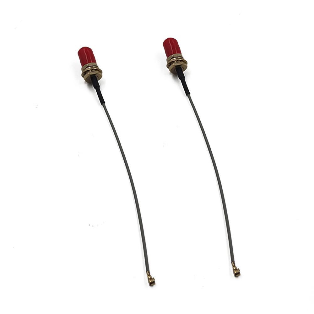
In GNSS RF pigtail assemblies, the cable construction typically includes a silver-plated copper-clad steel center conductor, low-loss PTFE dielectric, and tin-overcoated copper shield braiding, which minimizes signal leakage while maintaining flexibility.
Selecting the Right Cable Type for Your GNSS Application
Short-Run Applications (Under 1 Meter)
For short cable runs under 1 meter, RG174 and RG316 cables are the most common choices. Their small diameter, high flexibility, and adequate attenuation characteristics make them ideal for internal routing within enclosures, connecting GNSS modules to antennas in compact devices, and test setups. RG316 offers slightly better attenuation than RG174 (0.85 dB/m versus 0.97 dB/m at 1 GHz) and is often preferred for applications where signal integrity is particularly critical.
Medium-Run Applications (1 to 5 Meters)
For medium-distance cable runs, RG58 and LMR-195 are popular choices. RG58 offers a good balance of low signal loss and flexibility, with an attenuation of approximately 0.92 dB/m. LMR-195 provides significantly lower loss and is suitable for antenna feeder runs and inter/intra cabinet jumpers.
Long-Run Applications (Over 5 Meters)
For cable runs exceeding 5 meters, the choice of cable becomes increasingly critical. Every additional meter of cable introduces more attenuation, and the cumulative loss can quickly exceed the acceptable limits for GNSS receivers. In these applications, LMR-400 or similar low-loss cables are recommended. The Trimble LMR-400 coaxial cable, for example, is a high-performance, low-loss RF cable engineered for demanding geospatial and surveying applications, ideal for connecting GNSS antennas over extended distances.
The IGS guidelines emphasize that the cable type must be sufficient for the intended cable run, and it is recommended to use high-quality low-loss cables with a loss of less than 0.2 dB/m at the L1 frequency, while minimizing the total cable length and the number of connectors.
The Role of Cable Assemblies in Different GNSS Applications
Automotive and Telematics
The automotive industry represents one of the fastest-growing markets for GNSS RF pigtail cable assemblies. Modern vehicles incorporate GNSS for navigation, telematics, advanced driver assistance systems (ADAS), and vehicle-to-everything (V2X) communication. FAKRA cable assemblies are the standard in this environment, offering high-performance signal transmission with robust mechanical characteristics.
Amphenol RF has expanded its automotive portfolio with high-flex RG-58 FAKRA cable assemblies designed for vehicle communication systems, including those used across electric and hybrid platforms. These pre-configured assemblies are built using RG-58 cable and are intended for use in automotive communication systems, GNSS/GPS, telematics, infotainment platforms, and other radio frequency-based vehicle technologies. The 50-ohm assemblies support performance up to 3 GHz and are engineered to maintain consistent signal integrity while exposed to repeated flexing and vibration.
IoT and Embedded Systems
The Internet of Things (IoT) has created enormous demand for compact, reliable GNSS RF pigtail cable assemblies. IoT devices ranging from asset trackers and wearables to smart agriculture sensors and industrial monitoring equipment all require GNSS connectivity in increasingly smaller form factors.
In these applications, U.FL/IPEX and MMCX connectors are the norm, paired with micro-coaxial cables such as 1.13 mm and RG178. These assemblies are typically used in antenna applications, LoRa modules, Mini PCI cards, Bluetooth modules, Wi-Fi radios, and GPS modules. The compact form factor and flexibility of these assemblies are ideal for internal routing, test setups, and installations where rigid connections are not practical.
Surveying and High-Precision Positioning
Surveying, geodesy, and precision agriculture applications demand the highest levels of GNSS accuracy, often requiring multi-frequency, multi-constellation receivers with RTK or PPP capabilities. In these applications, the cable assembly must deliver exceptional signal fidelity with minimal loss and phase distortion.
For RTK systems, the total feeder attenuation is typically recommended to be within 3 dB. LMR-200 and LMR-400 cables are commonly used in these applications, often paired with high-quality SMA or TNC connectors. The use of low-loss cables is particularly important because the GNSS receiver's RF input gain requirements must be met after accounting for cable and connector losses. For optimal GNSS tracking and TerraStar L-band reception, a cascaded antenna gain of +25 dB to +35 dB is recommended, and the maximum RF input gain supported by modern receivers ranges from +15 dB to +55 dB depending on firmware version.
Industrial and Outdoor Installations
Industrial GNSS applications, including fleet management, construction equipment, mining vehicles, and precision agriculture, often require cable assemblies that can withstand harsh environmental conditions. IP67, IP68, and IP69K-rated assemblies are essential in these environments, providing protection against dust, water ingress, and extreme temperatures.
Amphenol RF offers MCX cable assemblies with rugged IP67-rated bulkhead SMA, TNC, RP-TNC, and N-Type straight jacks, designed for GPS/GNSS, IoT, wireless communications, and industrial applications. GCT's RF cable assemblies are available with IP67, IP68, and IP69K protection (mated and unmated) and feature up to 6 GHz frequency and 50-ohm impedance.
Installation Best Practices for GNSS RF Pigtail Cable Assemblies
Cable Routing and Stress Management
Proper cable routing is essential for maintaining signal integrity and ensuring long-term reliability. The IGS guidelines recommend using the shortest possible cable length with the fewest connectors and no stress on the cable. Cable tension at the receiver and antenna connections can stress the connectors, leading to connection failure or intermittent connectivity. At the antenna end, this tension can also cause antenna rotation, which degrades positioning accuracy.
It is recommended to leave a small amount of slack cable at both the antenna and receiver connections to relieve tension. When using a high-grade, less flexible cable for the main trunk, a shorter, more flexible lower-grade cable at the antenna or receiver connections can help reduce stress.
Environmental Protection
GNSS antennas are frequently mounted outdoors, exposing the cable assembly to weather, UV radiation, insects, and other environmental hazards. Cable connectors are particularly vulnerable to failure when exposed to stress, corrosion, or the ingress of water, dust, and pests.
To protect cable assemblies in outdoor installations, self-fusing UV-stabilized tape should be used to seal antenna cable connectors against water ingress and UV radiation. Proper conduit or cable trays should be used to protect cables from physical damage. In lightning-prone areas, horizontal cable runs should be minimized to reduce the risk of signal induction from nearby lightning strikes, and grounded lightning protectors should be installed.
Connector Mating and Torque
Proper connector mating is critical for achieving specified electrical performance. Connectors should be tightened to the manufacturer's recommended torque specifications — too little torque can result in intermittent connections, while too much torque can damage the connector or cable. For SMA connectors, the recommended torque is typically 0.8 to 1.1 N·m (7 to 10 in-lbs). For N-Type connectors, the recommended torque is typically 1.1 to 1.4 N·m (10 to 12 in-lbs).
When mating connectors, it is important to hold the pigtail connectors during cable attachment and avoid all tension, torsion, and bending forces that could damage the connection.
Industry Standards and Certifications
MIL-SPEC Standards
For defense, aerospace, and other high-reliability applications, GNSS RF pigtail cable assemblies must comply with stringent military specifications. The key standards include MIL-DTL-17 (formerly MIL-C-17), which defines the construction, materials, and performance of RF coaxial cables used in mission-critical systems. Only cables listed on the military's Qualified Products List (QPL) are considered true MIL-SPEC cables.
MIL-PRF-39012 covers the general requirements for coaxial RF connectors, while MIL-STD-348 defines the interface dimensions for RF connectors. These standards ensure interoperability between components from different manufacturers and guarantee performance under extreme environmental conditions.
IEC Standards
The International Electrotechnical Commission (IEC) publishes standards for radio frequency and coaxial cable assemblies. IEC 60966-2-6, for example, is a detail specification for cable assemblies for radio and TV receivers that covers return loss requirements, insertion loss requirements, and screening effectiveness measurement methods. IEC 62153-4-7 defines the triaxial method for measuring screening effectiveness, which is particularly important for GNSS applications where interference rejection is critical.
RoHS and Environmental Compliance
Most GNSS RF pigtail cable assemblies are RoHS (Restriction of Hazardous Substances) compliant, meaning they do not contain lead, mercury, cadmium, hexavalent chromium, polybrominated biphenyls (PBB), or polybrominated diphenyl ethers (PBDE) above specified thresholds. This compliance is increasingly important for products sold in the European Union and other markets with similar environmental regulations.
Market Trends and Future Outlook
The global RF coaxial cable assembly market is experiencing robust growth, driven by increasing demand for GNSS-enabled devices, the expansion of 5G networks, and the proliferation of IoT applications. According to market research, the RF coaxial cable assembly market was valued at approximately US$4.46 billion in 2025 and is projected to reach US$6.97 billion by 2032, reflecting a compound annual growth rate (CAGR) of 6.6% during the forecast period. Other analysts project even higher growth, with the market expanding from US$4.14 billion in 2025 to US$6.54 billion by 2031 at a CAGR of 7.9%.
Asia represents the largest regional market for RF coaxial cable assemblies, valued at approximately US$898.88 million in 2025, followed by North America at US$872.36 million and Europe at US$679.65 million. This distribution reflects the concentration of electronics manufacturing in Asia, particularly in China, Taiwan, and South Korea, as well as the strong demand from the automotive and telecommunications sectors in North America and Europe.
Key players in the market include TE Connectivity, Molex, Amphenol, Gore, Rosenberger, Huber+Suhner, Sumitomo, Winchester Interconnect, Volex Group, Proterial, Radiall, Nexans, SPINNER Group, and Axon' Cable. These companies compete on the basis of performance, reliability, customization capabilities, and cost.
Looking ahead, several trends are expected to shape the GNSS RF pigtail cable assembly market:
Miniaturization: As GNSS modules become smaller and more integrated, demand for ultra-miniature cable assemblies with U.FL/IPEX connectors and micro-coaxial cables will continue to grow.
Higher Frequency Support: The adoption of L5 and L6 GNSS signals, as well as the integration of GNSS with 5G and other wireless technologies, is driving demand for cable assemblies that can support higher frequencies with low loss.
Increased Environmental Requirements: As GNSS finds its way into more outdoor and industrial applications, demand for IP67, IP68, and IP69K-rated assemblies will increase.
Automotive Integration: The continued growth of electric and autonomous vehicles will drive demand for high-flex, vibration-resistant FAKRA cable assemblies.
Choosing the Right Partner for GNSS RF Pigtail Cable Assemblies
The GNSS RF pigtail cable assembly is a deceptively simple component that plays an outsized role in the performance of satellite navigation systems. From the choice of coaxial cable to the selection of connectors, environmental protection, and compliance with industry standards, every decision has consequences for signal integrity, positioning accuracy, and system reliability.
For engineers and system integrators, the key takeaways are clear: prioritize low insertion loss and stable impedance across the GNSS frequency band; choose cable types appropriate for the required run length and environmental conditions; use connectors that match the application's mechanical and electrical requirements; and ensure proper installation practices to protect the assembly from stress and environmental hazards.
As the GNSS market continues to expand — driven by automotive, IoT, surveying, and industrial applications — the demand for high-quality RF pigtail cable assemblies will only grow. Working with an experienced manufacturer that offers both standard products and custom cable assembly services can help ensure that your GNSS system achieves the performance and reliability it requires. Whether you need a simple RG174 pigtail for an embedded GNSS module or a ruggedized LMR-400 assembly for a permanent outdoor installation, the right cable assembly is out there — and understanding the technology behind it is the first step toward making the right choice.
Lucy Yang | lucy.y@toxutech.com
Dotty Zhao | sales04@toxutech.com
Global Business Director / Sales Team / Global Operations


 En
En Cn
Cn Korean
 Home >