

-
Products -PCBA Manufacturing RF Connectors RF Cable Assemblys Embedded Antennas External Antennas GNSS Positioning Solutions
RF Connectors

RF Cable Assemblys
Embedded Antennas
External Antennas
GNSS Positioning Solutions































 Language


Language


Time:2026-10-15 Views:0
Why L1/L2/L5 Antennas Define Modern Surveying Accuracy
In the world of professional surveying, the GNSS antenna is often the most underestimated component in the positioning chain. You can pair a $5,000 receiver with a substandard antenna and achieve worse results than a $500 receiver connected to a properly engineered survey-grade antenna. This reality underscores a fundamental truth: the antenna determines signal quality before the receiver ever processes it .
For surveying professionals, the choice of frequency bands is no longer a simple matter of “L1 is enough.” The modern GNSS landscape has evolved dramatically. Multi-constellation support—GPS, GLONASS, Galileo, BeiDou, QZSS, and NavIC—combined with multi-frequency reception across L1, L2, and L5 bands has become the baseline requirement for centimeter-level RTK and static surveying applications .
This article provides a comprehensive technical deep-dive into L1/L2/L5 GNSS antennas designed specifically for surveying applications. We will explore why these three bands matter, what technical specifications truly distinguish a professional survey antenna from consumer-grade alternatives, and how to select the optimal antenna for your specific surveying workflow.
Understanding the L1, L2, and L5 Frequency Bands
L1: The Foundational Band (1575.42 MHz)
The L1 band has been the primary frequency for GPS since its inception and remains the most widely used GNSS signal globally. At 1575.42 MHz, L1 carries the Coarse/Acquisition (C/A) code and the precise P(Y) code, along with modernized civilian signals like L1C. Virtually every GNSS constellation operates a signal in the L1 frequency range, including GPS L1, Galileo E1, BeiDou B1C, and QZSS L1 .
For surveying purposes, L1 alone is insufficient for high-precision work. While L1 provides the foundation for satellite acquisition and rough positioning, single-frequency observations cannot effectively mitigate ionospheric delays—the largest error source in GNSS positioning after atmospheric effects.
L2: The Precision Workhorse (1227.60 MHz)
The L2 band, centered at 1227.60 MHz, was originally designed for military use but has become indispensable for high-precision civilian surveying through techniques like dual-frequency ionospheric correction. By comparing L1 and L2 observations, receivers can estimate and eliminate the frequency-dependent ionospheric delay, a technique that reduces positioning error from meters to centimeters .
The availability of L2 signals across GPS, GLONASS (G2), Galileo (E5b), and BeiDou (B2) enables faster ambiguity resolution and more reliable RTK solutions, particularly over longer baselines where ionospheric effects become pronounced.
L5: The Modern Standard for Robustness (1176.45 MHz)
The L5 band represents the newest generation of GNSS signals. Operating at 1176.45 MHz, L5 offers several decisive advantages for surveying applications:
Higher signal power: L5 signals are transmitted at higher power levels than L1, improving reception in challenging environments .
Wider bandwidth: The wider bandwidth of L5 signals provides better resistance to multipath interference .
Advanced modulation: L5 uses a different modulation scheme that enhances tracking robustness.
Galileo’s E5a, BeiDou’s B2a, and NavIC’s L5 signals also occupy this frequency range, creating a broad ecosystem of compatible signals. The combination of L1, L2, and L5 enables triple-frequency ionospheric correction, which significantly accelerates integer ambiguity resolution and improves positioning reliability even under adverse conditions .
Core Technical Specifications That Define a Survey-Grade L1/L2/L5 Antenna
Phase Center Stability: The Millimeter Battle
The phase center of a GNSS antenna is the apparent point from which signals are received. In reality, this point shifts depending on the satellite’s elevation angle and frequency—a phenomenon known as Phase Center Variation (PCV). The average position is the Phase Center Offset (PCO) .
For professional surveying, phase center stability is arguably the single most important specification. A drift of even a few millimeters in the phase center translates directly into positioning error. Survey-grade L1/L2/L5 antennas typically achieve phase center errors of ±2mm or better, with some high-end models specifying ±1mm accuracy .
Antennas with well-calibrated phase centers often come with ANTEX and ANTINFO files recognized by the International GNSS Service (IGS), enabling surveyors to apply precise corrections in post-processing software .
Multipath Suppression: Defeating the “Echo Problem”
Multipath interference occurs when GNSS signals reflect off nearby surfaces—buildings, vehicles, water, or even the ground—before reaching the antenna. These reflected signals arrive delayed and phase-shifted, corrupting the direct signal and degrading positioning accuracy .
Survey-grade antennas employ several strategies to combat multipath:
Choke ring structures: Concentric metallic rings create a high-impedance surface that attenuates low-elevation reflected signals by 15-20 dB relative to zenith signals . This is the gold standard for base stations and permanent reference installations.
Advanced ground planes: A large, well-designed ground plane (typically 100-150mm diameter) shields the antenna element from below-horizon signals and provides a stable reference for the radiating element .
Specialized antenna elements: Designs like the Pinwheel® and multi-point feeding architectures create radiation patterns that naturally reject cross-polarized reflected signals .
Polarization Purity and Axial Ratio
GNSS satellites transmit Right-Hand Circular Polarized (RHCP) signals. A high-quality survey antenna must efficiently receive RHCP while rejecting Left-Hand Circular Polarized (LHCP) signals—which is exactly what most reflected multipath signals become .
The axial ratio quantifies polarization purity. An ideal circularly polarized antenna has an axial ratio of 0 dB. In practice, axial ratios below 3 dB are considered excellent for survey applications . Lower axial ratios mean cleaner signal reception and better multipath rejection.
Gain Pattern and Low-Elevation Performance
While peak gain specifications often attract attention, the gain consistency across elevation angles matters far more for surveying. A survey antenna should maintain stable gain from zenith down to at least 10° elevation, with no more than 8 dB roll-off .
This characteristic ensures that low-elevation satellites—which are crucial for maintaining robust geometry and redundancy in the position solution—remain usable. In urban canyons or partially obstructed sites, this low-elevation performance directly impacts the number of satellites available and, consequently, the reliability of the RTK fix.
LNA Performance: Noise Figure and Gain
A GNSS antenna is an active system: the radiating element is paired with a Low Noise Amplifier (LNA) that boosts the signal before it travels down the cable to the receiver .
LNA gain: Typically 25-40 dB. Too little gain and cable losses overwhelm the signal; too much gain can saturate the receiver front-end, especially near cellular towers .
Noise figure: Below 2 dB is acceptable, below 1.5 dB is good, and below 1.0 dB is excellent. Every 0.5 dB of noise figure degradation directly reduces the Carrier-to-Noise ratio (C/N₀) that the receiver can achieve .
For base station installations with long cable runs, higher LNA gain (38-40 dB) compensates for cable attenuation and maintains signal integrity .
Survey Antennas vs. Standard GNSS Antennas: What Sets Them Apart
Understanding the distinction between a professional survey antenna and a standard GNSS antenna is essential for making informed procurement decisions.
| Characteristic | Standard GNSS Antenna | Survey-Grade L1/L2/L5 Antenna |
|---|---|---|
| Frequency Support | L1 only, or L1+L2 | L1+L2+L5 (triple-band) |
| Phase Center Stability | Large, unpredictable PCV | ±2 mm or better PCV, calibrated |
| Multipath Rejection | Limited or none | Choke ring, advanced ground plane |
| Accuracy | Meter-level | Centimeter to millimeter-level |
| Construction | Compact, lightweight | Robust, weatherproof, larger |
| Cost | $10–100 | $150–2,500+ |
Standard GNSS antennas prioritize compact size and low cost for consumer applications like vehicle navigation, smartphones, and asset tracking . Survey antennas, by contrast, are engineered for repeatability, precision, and reliability under demanding field conditions .
The performance gap manifests most dramatically in multipath environments. Research conducted in construction and urban survey settings demonstrates that low-cost antennas suffer significantly greater degradation compared to survey-grade antennas when operating near buildings and reflective surfaces .
L1/L2/L5 Antenna Architectures: Choosing the Right Design
Patch Antennas with Ground Planes
The most common survey antenna architecture combines a ceramic patch element with a substantial ground plane. The SPK6618H, for example, incorporates a 130mm ground plane with six hybrid couplers to achieve precise signal phasing . This design offers excellent performance at a reasonable cost and is widely used for RTK base stations and rover applications.
Choke Ring Antennas
For permanent reference stations and the most demanding survey applications, choke ring antennas represent the pinnacle of multipath suppression. The concentric rings create a high-impedance boundary that effectively blocks ground reflections. These antennas are larger, heavier, and more expensive, but deliver unmatched phase center stability and signal purity .
Helical and Quadrifilar Designs
Helical antennas offer consistent gain patterns regardless of orientation, making them suitable for handheld survey devices and applications where the antenna may tilt. While typically offering slightly less multipath rejection than choke ring designs, they provide a good balance of performance and portability .
The Survey Dome (UFO) Design
The recognizable “UFO” or dome-shaped survey antenna has become an industry standard for a reason. Its large ground plane and optimized radome provide excellent weather protection, stable phase center performance, and effective multipath suppression. Models like the SPK6618H are NGS-certified and come with official calibration data, making them suitable for the most rigorous surveying applications .
Practical Selection Guide: Matching Antenna to Application
RTK Base Station (Permanent or Semi-Permanent)
For a fixed base station, prioritize phase center stability, multipath rejection, and environmental durability. A choke ring antenna or a high-quality survey dome with a large ground plane is ideal. The antenna should support all available bands (L1/L2/L5 plus L-band for PPP corrections) and ideally carry IGS or NGS certification .
Key specifications to verify:
Phase center error: ≤2mm
Axial ratio: ≤3 dB
IP rating: IP67 or better
Operating temperature: -40°C to +85°C
RTK Rover (Survey Pole)
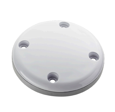
For rover applications, weight and mounting compatibility become important alongside performance. The antenna must use the standard 5/8"-11TPI mounting thread found on surveying poles . A high-quality survey dome or compact choke ring design works well.
UAV/Drone Surveying
Weight becomes critical. While a full survey dome may be too heavy, compact L1/L2/L5 antennas with integrated ground planes can deliver excellent results. Research has demonstrated that low-cost dual-frequency receivers paired with ground-plane antennas can achieve centimeter-level precision even at high latitudes .
Machine Control and Construction
For construction machinery, durability and vibration resistance are paramount. The antenna should have a robust radome, wide operating temperature range, and secure mounting. A survey-grade dome antenna with high LNA gain (38-40 dB) ensures reliable performance even with longer cable runs .
Installation Best Practices for L1/L2/L5 Survey Antennas
Ground Plane Considerations
Even the best antenna can be compromised by poor installation. The antenna should be mounted on a conductive ground plane at least 100mm in diameter, preferably larger. This ground plane shields the antenna from below-horizon signals and provides a stable reference for the radiating element .
Cable Selection and Routing
Use low-loss coaxial cable appropriate for the run length:
≤20m: RG-142 or LMR-240
20-50m: LMR-400
>50m: Consider a line amplifier or fiber optic extension
Ensure proper impedance matching (50Ω) throughout the signal chain .
Avoiding Interference Sources
Keep the antenna away from:
Cellular and radio transmitters
High-power electrical equipment
Reflective surfaces that create multipath
Sources of vibration that could affect phase stability
Surveying Pole Setup
For RTK rovers, use a fixed-height surveying pole and ensure the antenna is mounted perpendicular to the pole. Most professional antennas include a bubble level or can be paired with one. The antenna reference point (ARP) should be clearly marked and its offset above the ground point documented.
The Economic Case for L1/L2/L5 Survey Antennas
While survey-grade antennas cost significantly more than consumer alternatives, the economic argument for professional equipment is compelling when total project costs are considered.
A survey-grade antenna with NGS certification and published calibration data enables:
Faster ambiguity resolution: Triple-frequency signals accelerate RTK initialization
Reduced re-survey costs: Reliable centimeter-level accuracy minimizes the need for repeat measurements
Longer baseline capability: Multi-frequency ionospheric correction extends the effective range from a base station
All-weather reliability: IP67-rated construction ensures operation in rain, dust, and temperature extremes
The SPK6618H, for example, offers NGS certification and full L1/L2/L5/E6 support at approximately $170—a fraction of the cost of traditional survey-brand antennas while delivering professional-grade performance .
The evolution of GNSS from single-frequency L1 to multi-band L1/L2/L5 operation has transformed what surveyors can achieve in the field. Triple-frequency antennas enable faster RTK fixes, more reliable performance in challenging environments, and the centimeter-level precision that modern projects demand.
When selecting an L1/L2/L5 antenna for surveying, resist the temptation to cut corners on this critical component. The antenna is the first element in the signal chain—and the one that determines the quality of everything that follows. Prioritize phase center stability, multipath rejection, and verified specifications over marketing claims. Look for antennas with published calibration data, NGS or IGS certification, and documented performance in real-world survey conditions.
Whether you are establishing a permanent CORS station, equipping a survey rover fleet, or integrating GNSS into autonomous construction equipment, the right L1/L2/L5 antenna is not an expense—it is the foundation upon which your positioning accuracy rests.
Lucy Yang | lucy.y@toxutech.com
Dotty Zhao | sales04@toxutech.com
Global Business Director / Sales Team / Global Operations


 En
En Cn
Cn Korean
 Home >