

-
Products -PCBA Manufacturing RF Connectors RF Cable Assemblys Embedded Antennas External Antennas GNSS Positioning Solutions
RF Connectors

RF Cable Assemblys
Embedded Antennas
External Antennas
GNSS Positioning Solutions































 Language


Language


Time:2026-10-15 Views:0
Why Compact GNSS PCBA Cable Assembly Matters
In the rapidly evolving world of satellite navigation technology, the demand for smaller, more efficient, and highly integrated positioning solutions has never been greater. From asset trackers and wearable devices to automotive telematics and IoT sensors, manufacturers across industries are seeking ways to embed precise location capabilities into increasingly compact form factors. At the heart of this trend lies a critical but often overlooked component: the compact GNSS PCBA cable assembly.
A compact GNSS PCBA cable assembly represents the convergence of three essential elements: a printed circuit board assembly (PCBA) that houses the GNSS receiver module, an integrated antenna system, and a carefully engineered cable assembly that connects the RF front-end to the host device. This integrated approach addresses one of the most persistent challenges in GNSS design: maintaining signal integrity and positioning accuracy while minimizing physical footprint.
For OEMs and system integrators, understanding the nuances of compact GNSS PCBA cable assemblies is no longer optional—it is essential for competitive product development. This comprehensive guide explores every facet of these assemblies, from the fundamental principles of GNSS signal reception to the practical considerations of cable selection, RF shielding, manufacturing standards, and future trends. By the end of this article, you will have a thorough understanding of how to specify, evaluate, and integrate compact GNSS PCBA cable assemblies into your next-generation products.
Understanding GNSS Technology: The Foundation
What Is GNSS and How Does It Work?
Global Navigation Satellite System (GNSS) is the overarching term for satellite-based navigation systems that provide autonomous geospatial positioning with global coverage. The most well-known GNSS is the United States' Global Positioning System (GPS), but the ecosystem now includes Russia's GLONASS, the European Union's Galileo, China's BeiDou (also known as Compass), and regional systems such as Japan's QZSS and India's NavIC.
GNSS receivers work by triangulating signals from multiple satellites. Each satellite broadcasts a signal containing its precise orbital position and timestamp. The receiver measures the time it takes for signals from at least four satellites to arrive, then calculates its distance from each satellite. Using trilateration, the receiver determines its three-dimensional position (latitude, longitude, and altitude) plus time.
The frequencies used by GNSS systems vary by constellation and signal type. GPS, for example, operates primarily on L1 (1575.42 MHz), L2 (1227.60 MHz), and L5 (1176.45 MHz) bands. Modern GNSS modules increasingly support multiple constellations and frequency bands simultaneously, a capability known as multi-constellation, multi-frequency positioning. This approach significantly improves accuracy, reduces time-to-first-fix (TTFF), and enhances reliability in challenging environments such as urban canyons.
The Critical Role of Antennas in GNSS Systems
The GNSS antenna is arguably the most performance-critical component in any positioning system. Satellite signals reaching the Earth's surface are extraordinarily weak—typically around -130 dBm, which is well below the thermal noise floor in many environments. The antenna must capture these faint signals with minimal degradation while rejecting interference from other RF sources.
GNSS antennas are typically Right-Hand Circularly Polarized (RHCP) and have a near-hemispherical reception pattern. This configuration allows them to receive signals from any azimuthal direction and from zenith to horizon, maximizing satellite visibility. Common antenna types include patch antennas (widely used in compact devices), helical antennas (favored for dynamic applications), and choke ring antennas (used in high-precision surveying).
The choice between passive and active antennas is another critical decision. Passive antennas, which contain no amplification circuitry, are simpler, more cost-effective, and suitable for short cable runs—typically under one meter. Active antennas incorporate a Low Noise Amplifier (LNA) and often filtering, allowing signals to travel over longer cables without degradation. For applications where the antenna must be located more than one meter from the receiver, active antennas are essential.
The Anatomy of a Compact GNSS PCBA Cable Assembly
PCBA: The Electronic Heart
The PCBA (Printed Circuit Board Assembly) in a compact GNSS assembly serves as the central integration platform. It typically includes several key components:
GNSS Receiver Module or Chipset: This is the core processing unit that demodulates satellite signals, performs position calculations, and outputs location data in standard formats such as NMEA 0183. GNSS modules vary widely in capability, from single-frequency GPS-only receivers to multi-constellation, multi-frequency engines capable of centimeter-level accuracy when paired with RTK corrections.
RF Front-End Circuitry: Between the antenna and the GNSS receiver lies the RF front-end, which may include filters (SAW filters are common), Low Noise Amplifiers (LNAs), and impedance matching networks. The design of this section is critical for maintaining signal quality and rejecting out-of-band interference. A typical compact GNSS front-end might employ a filter-LNA-filter topology to achieve both low noise figure and high out-of-band rejection.
Power Management: GNSS modules require stable, low-noise power supplies. In compact designs, careful power management is necessary to minimize noise coupling into the sensitive RF path while maintaining energy efficiency for battery-powered applications.
Interface and Connectivity: The PCBA provides the electrical interface between the GNSS subsystem and the host device. This may include UART, I2C, SPI, or USB interfaces for data communication, as well as control lines for power management and antenna supervision.
Integrated Antenna Design
In compact GNSS PCBA assemblies, the antenna is often integrated directly onto the PCB or placed in close proximity. This integration presents both opportunities and challenges.
The most common approach for compact devices is the ceramic patch antenna, which offers a good balance of size, performance, and cost. These antennas are typically mounted on the PCB surface and require careful attention to ground plane sizing and placement. The ground plane acts as a counterpoise for the antenna and significantly affects its radiation pattern and efficiency.
For even more compact designs, chip antennas or FPC (Flexible Printed Circuit) antennas may be employed. These solutions sacrifice some performance for reduced size and easier integration into space-constrained enclosures. The trade-offs between antenna size, gain, bandwidth, and efficiency must be carefully evaluated based on the specific application requirements.
The Cable Assembly: More Than Just a Connection
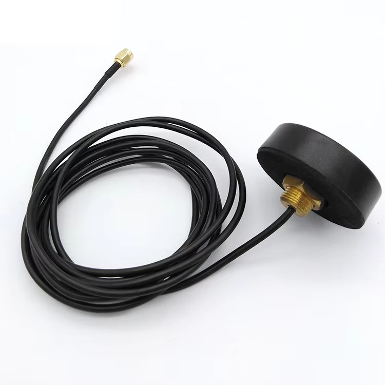
The cable assembly in a compact GNSS PCBA system is far more than a simple electrical connection. It is a critical RF transmission line that must preserve signal integrity from the antenna to the receiver with minimal loss and interference.
Cable Types: Coaxial cables are standard for GNSS applications due to their excellent shielding and controlled impedance characteristics. Common types include RG-174 (thin, flexible, moderate loss), RG-316 (slightly larger, lower loss), and specialized low-loss cables for longer runs. The choice depends on cable length, frequency requirements, and mechanical constraints.
Connectors: The connectors at each end of the cable assembly must match the impedance of the cable (typically 50 ohms) and provide reliable, low-loss connections. Common connector types for GNSS applications include SMA, TNC, MCX, IPEX (also known as U.FL), and FAKRA (for automotive applications). The selection depends on the mating interface, space constraints, and environmental requirements.
Assembly Quality: Poor cable assembly can introduce impedance mismatches, signal reflections, and insertion losses that degrade GNSS performance. High-quality assembly processes ensure proper connector attachment, controlled cable routing, and minimal stress on solder joints. For automotive and industrial applications, cable assemblies must also withstand vibration, temperature cycling, and moisture exposure.
Why Compact Form Factor Matters in Modern GNSS Applications
Space Constraints in IoT and Wearable Devices
The Internet of Things (IoT) revolution has created unprecedented demand for miniature positioning solutions. Asset trackers, pet collars, wearable health monitors, and smart tags all require GNSS capabilities in packages that may be smaller than a matchbox. In these applications, every cubic millimeter counts, and the ability to integrate a complete GNSS subsystem—including antenna, receiver, and interface—into a compact PCBA cable assembly is essential.
Traditional GNSS receiver boards, which often measure several centimeters square and require external antenna connections, are simply too large for these applications. Compact PCBA assemblies address this by integrating the antenna and receiver into a single, miniaturized package that can be easily embedded into the host device.
Performance Considerations in Miniaturized Designs
Miniaturization inevitably introduces performance trade-offs. Smaller antennas have narrower bandwidth, lower gain, and reduced efficiency compared to their larger counterparts. Ground plane size, which is often constrained in compact devices, directly affects antenna radiation patterns and impedance matching.
To mitigate these challenges, designers employ several strategies. Multi-band antenna designs allow a single compact antenna to cover L1 and L5 frequencies, improving resistance to multipath and ionospheric delays. Active antenna designs compensate for small antenna size by incorporating low-noise amplification. Careful RF layout and shielding minimize interference from digital circuitry within the compact assembly.
The cable assembly also plays a role in managing these trade-offs. By allowing the antenna to be positioned optimally—away from noise sources and with a clear view of the sky—while keeping the receiver in a convenient location, the cable assembly enables better overall system performance than a fully integrated, single-board solution might achieve.
The Demand for Faster Time-to-Market
In today's competitive electronics landscape, speed to market can determine a product's success. Compact GNSS PCBA cable assemblies offer significant advantages in this regard. Rather than designing a GNSS subsystem from scratch—selecting components, designing RF circuits, tuning antennas, and validating performance—OEMs can integrate a pre-designed, pre-validated assembly that is ready for deployment.
This "drop-in" approach reduces development risk and accelerates product timelines. The assembly vendor has already addressed the complex RF challenges, allowing the OEM to focus on their core competencies. For companies without deep RF engineering expertise, this is particularly valuable.
Key Components of a High-Quality Compact GNSS PCBA Cable Assembly
GNSS Module Selection: Single vs. Multi-Constellation
The GNSS module at the heart of the assembly determines its fundamental capabilities. Single-constellation modules (GPS-only, for example) are simpler and less expensive but may struggle in environments with limited sky visibility. Multi-constellation modules that track GPS, GLONASS, Galileo, and BeiDou simultaneously offer improved satellite availability, faster fix times, and better performance in challenging conditions.
Multi-frequency support is another important consideration. Dual-frequency GNSS (typically L1 + L5) provides significant advantages in urban environments, where L5 signals are more resistant to multipath reflections and atmospheric delays. For high-precision applications such as surveying or autonomous navigation, dual-frequency is essential.
Antenna Technologies for Compact Designs
The antenna is often the limiting factor in compact GNSS performance. Several antenna technologies are available for compact PCBA assemblies:
Ceramic Patch Antennas: These are the workhorses of compact GNSS. They offer reasonable performance in a small package, are relatively inexpensive, and can be tuned for specific frequency bands. However, they require a ground plane of adequate size and can be sensitive to nearby components.
Chip Antennas: Surface-mount chip antennas are extremely compact and easy to integrate, but their performance is generally inferior to patch antennas. They are best suited for applications with modest accuracy requirements and favorable signal environments.
FPC Antennas: Flexible printed circuit antennas can be shaped and positioned to fit unusual enclosures. They offer design flexibility but require careful impedance matching and can be sensitive to nearby conductive surfaces.
Helical Antennas: While larger than patch antennas for equivalent performance, helical antennas offer excellent circular polarization and can be designed for very wide bandwidth. They are often used in handheld and portable devices where their omnidirectional pattern is advantageous.
LNA and Filter Integration
For active antenna configurations, the LNA and filter are critical for system performance. The LNA sets the noise figure of the entire receiver chain—a key parameter that determines how well weak satellite signals can be detected. A well-designed LNA for GNSS applications must provide high gain (typically 15-30 dB), low noise figure (typically under 1.5 dB), and excellent linearity to avoid intermodulation distortion.
SAW filters are commonly used in GNSS front-ends to reject out-of-band interference from cellular, Wi-Fi, and other RF sources. In compact designs, these filters must be carefully selected to provide adequate rejection without introducing excessive insertion loss. The classic topology is filter-LNA-filter, which provides good rejection on both sides of the LNA.
Power for the LNA is typically supplied through the same coaxial cable that carries the RF signal, a technique known as "bias tee" or "phantom power." The receiver provides DC voltage on the center conductor, which is separated from the RF path at the antenna end by an inductor or bias network. Current sensing circuits in the receiver can detect antenna presence and short circuits by monitoring the DC current draw.
Cable and Connector Selection
The cable and connectors must be selected based on several factors:
Frequency Range: The cable must have acceptable loss across all GNSS frequencies in use (typically 1.1 GHz to 1.6 GHz for multi-band systems).
Cable Length: Longer cables introduce more loss. For passive antennas, cable length is typically limited to about one meter. Active antennas can drive longer cables, but the LNA gain must be sufficient to overcome cable loss while not overloading the receiver input.
Impedance: 50 ohms is the standard impedance for GNSS RF paths. All components—cable, connectors, PCB traces—must maintain this impedance to avoid signal reflections.
Environmental Requirements: Automotive applications require cables and connectors that withstand temperature extremes, vibration, and chemicals. Industrial applications may require similar ruggedization. IP67-rated connectors and cable assemblies are available for outdoor and harsh-environment applications.
Connector Types: Common choices include SMA (threaded, reliable, moderately sized), MCX and MMCX (snap-on, compact), IPEX/U.FL (ultra-miniature, for board-to-board connections), and FAKRA (automotive-standard, color-coded). The selection depends on the mating interface, space constraints, and number of mating cycles required.
RF Layout and Shielding
Successful integration of a compact GNSS PCBA assembly requires careful attention to RF layout and shielding. Key considerations include:
Ground Plane: The ground plane beneath the antenna should be as large as possible and free of slots or discontinuities. For patch antennas, the ground plane size directly affects gain and bandwidth.
Separation: The GNSS antenna should be positioned as far as possible from noise sources such as switching power supplies, digital circuits, and communication radios (cellular, Wi-Fi, Bluetooth).
Shielding: In dense designs, a metal shield can may be necessary to isolate the GNSS front-end from interference. The shield must be properly grounded and designed to avoid resonances within the GNSS frequency bands.
Trace Impedance: The RF trace from the antenna to the receiver must maintain 50-ohm impedance. This requires careful stack-up design and trace geometry calculation.
Cable Routing and Strain Relief
The cable assembly is often the most vulnerable part of the GNSS system. Proper routing and strain relief are essential for reliability:
Avoid sharp bends that can damage the cable or change its impedance characteristics.
Provide strain relief at both the antenna and receiver ends to prevent stress on solder joints.
Route cables away from noise sources and maintain adequate separation from power and digital signal lines.
For applications with vibration, use cables with stranded conductors and secure them with appropriate clips or ties.
Grounding Strategies for Noise Reduction
Proper grounding is critical for GNSS performance. Poor grounding can introduce noise into the sensitive RF path, degrade antenna performance, and cause receiver desensitization. Best practices include:
Use a single, solid ground plane for the GNSS receiver and RF circuitry.
Avoid ground loops by ensuring that the antenna ground and receiver ground are connected at a single point.
For active antennas, the DC return path should be carefully designed to avoid noise coupling.
Testing and Validation
Thorough testing is essential to ensure that the compact GNSS PCBA cable assembly meets performance requirements. Key tests include:
Noise Figure Measurement: To verify that the LNA and front-end are performing as designed.
Gain and Radiation Pattern: To characterize antenna performance in the integrated assembly.
Out-of-Band Rejection: To confirm that filters are adequately rejecting interference.
Cold Start and TTFF: To measure how quickly the receiver acquires a position fix under various conditions.
Position Accuracy: To validate real-world performance against application requirements.
Applications Across Industries
Asset Tracking and Logistics
Asset trackers are among the most demanding applications for compact GNSS PCBA assemblies. These devices must be small enough to attach to packages, containers, or valuable equipment, yet provide reliable location data over extended periods. Battery life is a primary constraint, making power-efficient GNSS modules and duty-cycled operation essential.
In logistics applications, GNSS performance in challenging environments—inside warehouses, in urban delivery areas, and during transport—directly affects the value of the tracking data. Multi-constellation GNSS improves satellite availability, while L5 band support enhances performance in areas with signal reflections.
Automotive Telematics and Navigation
The automotive industry represents one of the largest markets for GNSS PCBA assemblies. From infotainment systems to emergency call (eCall) systems, from fleet management to autonomous driving, GNSS is fundamental to modern vehicles.
Automotive applications impose stringent requirements: wide temperature range (-40°C to +85°C or higher), resistance to vibration and shock, compliance with automotive quality standards (IATF 16949), and long-term supply stability. FAKRA connectors are standard for automotive RF connections, and cable assemblies must meet rigorous environmental specifications.
Wearables and Consumer Electronics
Smartwatches, fitness trackers, and portable navigation devices require GNSS in extremely compact form factors. These applications often employ chip antennas or small patch antennas, with careful attention to ground plane design and interference mitigation. Power efficiency is critical for battery-powered wearables, driving demand for low-power GNSS modules with advanced power management features.
IoT and Smart Agriculture
The IoT ecosystem encompasses a vast range of GNSS applications, from smart agriculture equipment to environmental monitoring stations. In precision agriculture, GNSS enables automated guidance, yield mapping, and variable-rate application of inputs. These applications often require higher accuracy than consumer-grade GNSS can provide, driving adoption of RTK-capable modules and dual-frequency antennas.
Drone and UAV Systems
Unmanned aerial vehicles rely on GNSS for navigation, stabilization, and mission planning. Compact GNSS PCBA assemblies are essential for weight-sensitive drone designs. The antenna must maintain performance despite the dynamic motion and changing orientation of the aircraft, making wide-bandwidth, circularly polarized antennas with good gain at low elevation angles particularly valuable.
Selection Criteria for OEMs and System Integrators
Performance Requirements
The starting point for selecting a compact GNSS PCBA cable assembly is a clear definition of performance requirements:
Accuracy: What positioning accuracy does the application require? Meter-level accuracy may suffice for asset tracking, while centimeter-level accuracy is needed for surveying or precision agriculture.
Time-to-First-Fix: How quickly must the system acquire a position fix? Cold start TTFF ranges from under 30 seconds for high-performance modules to several minutes for basic designs.
Update Rate: Does the application require high-frequency position updates (e.g., 10 Hz or higher for dynamic platforms)?
Sensitivity: What is the minimum signal level at which the receiver must operate? This determines requirements for antenna gain, LNA performance, and filtering.
Environmental Specifications
The operating environment dictates many design choices:
Temperature Range: Automotive and industrial applications require wider temperature ranges than consumer devices.
Ingress Protection: Outdoor applications may require IP67 or higher ratings for water and dust resistance.
Vibration and Shock: Transportation and industrial applications subject the assembly to mechanical stresses that must be accounted for in cable and connector selection.
EMI/EMC: Co-located radios (cellular, Wi-Fi) require careful filtering and shielding to prevent interference with GNSS reception.
Cost and Scalability
Cost is always a consideration, but it must be evaluated in the context of total system performance and reliability:
Volume: High-volume applications can justify custom designs with optimized component selection. Lower volumes may favor standard, off-the-shelf assemblies.
Assembly Complexity: More complex assemblies with active antennas, multiple filters, and precision connectors cost more but may be necessary for performance.
Supply Chain: Component availability and lead times can significantly affect total cost and production schedules. Working with a vendor that has established supply relationships is advantageous.
Vendor Capabilities and Support
The right manufacturing partner can make the difference between a successful product and a problematic one. Key vendor capabilities to evaluate include:
RF Engineering Expertise: The vendor should have demonstrated experience in GNSS and RF design, not just general electronics manufacturing.
Integration Services: The ability to integrate antenna, PCBA, and cable assembly into a complete, tested subsystem reduces customer engineering burden.
Quality Certifications: ISO 9001, IATF 16949 (for automotive), and other relevant certifications indicate a commitment to quality management.
Prototype and Production Support: The vendor should support both prototype development (fast turnaround, design feedback) and mass production (consistent quality, reliable delivery).
Market Trends and Future Developments
Miniaturization Continues
The trend toward smaller GNSS assemblies shows no signs of slowing. Advances in semiconductor integration are enabling more functionality in smaller packages—multi-band receivers, integrated LNAs, and even on-chip filtering. Antenna technology is also evolving, with metamaterial structures and advanced materials offering improved performance in smaller form factors.
Multi-Constellation and Multi-Frequency Adoption
Multi-constellation, multi-frequency GNSS is transitioning from high-end applications to mainstream adoption. The availability of low-cost dual-frequency modules is making L1+L5 positioning accessible for consumer and industrial applications. This trend improves performance in urban environments and enables new applications that were previously impractical.
Integration with Other Sensors
Modern positioning systems increasingly combine GNSS with other sensors—IMUs (Inertial Measurement Units), wheel tick sensors, and barometric altimeters—to maintain accurate positioning when GNSS signals are degraded or unavailable. This sensor fusion approach is particularly valuable for automotive and robotics applications. Compact GNSS PCBA assemblies may increasingly incorporate interfaces for these complementary sensors.
Regulatory and Standards Evolution
As GNSS becomes more pervasive, regulatory requirements are evolving. Automotive applications must comply with ISO 26262 functional safety standards. RF emissions and immunity are governed by regional regulations (FCC in the US, CE in Europe). For products sold in China, compliance with domestic standards for GNSS equipment is required. Manufacturers must stay informed of these requirements and select assemblies that meet applicable standards.
Making the Right Choice for Your Application
The compact GNSS PCBA cable assembly represents a sophisticated integration of RF engineering, antenna design, and manufacturing expertise. For OEMs and system integrators, these assemblies offer a path to faster development, reduced risk, and optimized performance in space-constrained applications.
Selecting the right assembly requires a thorough understanding of application requirements—accuracy, environmental conditions, size constraints, and cost targets. It also requires careful evaluation of potential vendors, looking beyond price to consider engineering capability, quality systems, and long-term supply reliability.
As GNSS technology continues to evolve toward multi-constellation, multi-frequency operation in ever-smaller packages, the compact PCBA cable assembly will remain a critical building block for location-aware products. By understanding the principles, trade-offs, and best practices outlined in this guide, engineers and product managers can make informed decisions that lead to successful products and satisfied customers.
Whether you are developing the next generation of asset trackers, automotive telematics systems, or precision agriculture equipment, the right compact GNSS PCBA cable assembly can be the foundation of your product's positioning performance. Choose wisely, and your product will benefit from reliable, accurate location data for years to come.
Lucy Yang | lucy.y@toxutech.com
Dotty Zhao | sales04@toxutech.com
Global Business Director / Sales Team / Global Operations


 En
En Cn
Cn Korean
 Home >